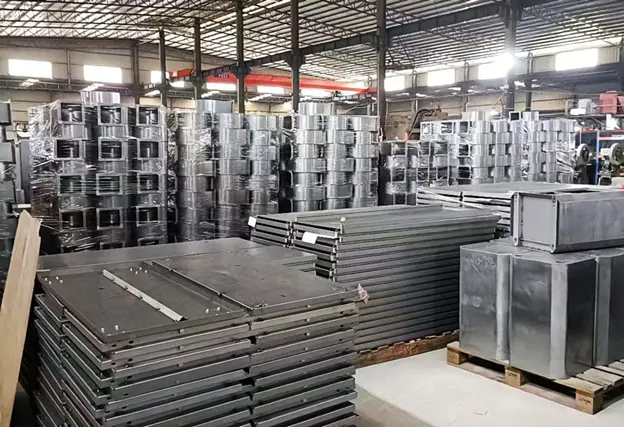
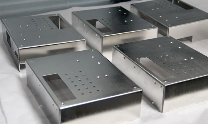
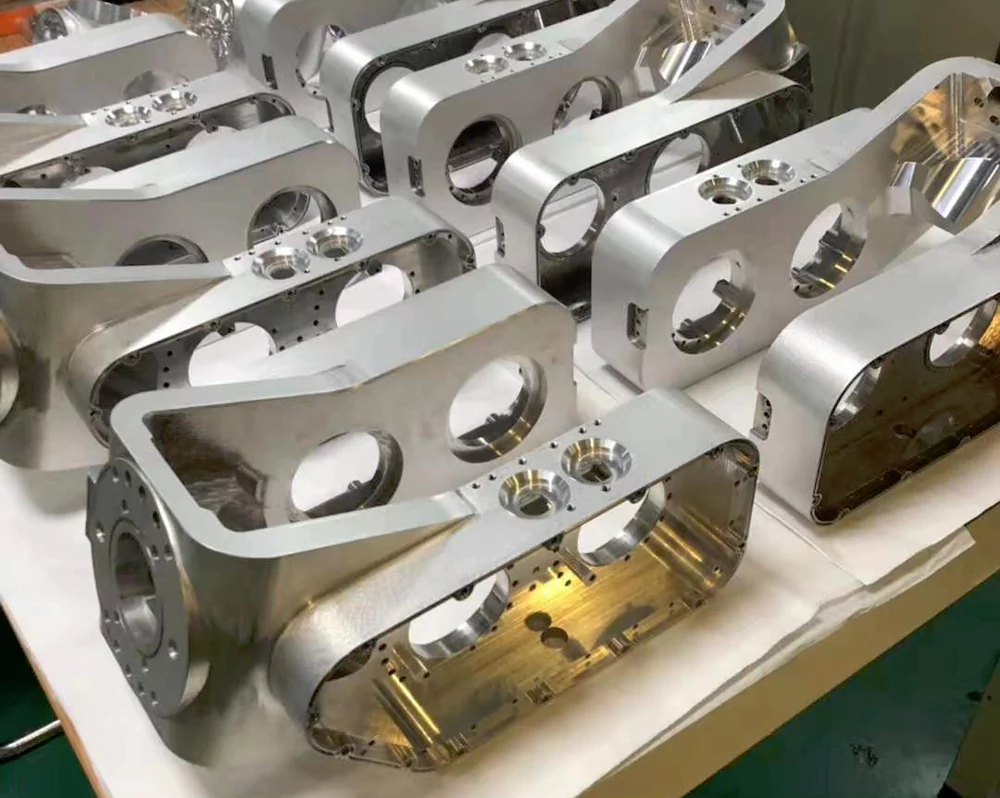
Sheet metal in industry and other areas is a widely used integrated cold working process. The processing object is generally less than 6mm thick sheet metal. The process includes key operations like folding, welding, riveting, splicing, and shaping.
The technologies include laser cutting, plasma cutting, water jet cutting, wire cutting, stamping, roll forming, sheet metal bending, forging, metal bonding, metal drawing, and precision welding.

Challenges in Traditional Sheet Metal Bending
Traditional bending processes reveal various issues, such as inadequate refinement during unfolding, reliance on mechanical cutting, and a complex process involving allowances, size adjustments, and final hole or groove completion.
These methods often result in low precision, inefficient material utilization, inconsistent products, and poor stability, impacting subsequent assembly quality.
Key Benefits of the Modern Process
Modern sheet metal bending utilizes laser cutting, CNC punching, and advanced automation technology, achieving high accuracy in the unfolding process.
This eliminates the need for mechanical cutting and ensures seamless transition into bending and shaping.
However, to maximize these benefits, high-precision sheet metal unfolding diagrams are crucial, emphasizing the importance of accurate drawings for optimal outcomes.
Common unfolding methods
The three-dimensional unfolding methods for sheet metal surfaces are often graphical, computational, experimental and comprehensive.
The traditional method of unfolding a bent sheet metal part is the calculation method.
The plastic deformation during bending is mainly concentrated in the bending area of the sheet metal part, which determines the size of the unfolding diagram to a certain extent different from the geometrically calculated dimensions, and independent calculations have to be carried out.
A number of factors, such as the thickness of the sheet metal part, affect the unfolding dimensions of the bent sheet metal part.
When calculating the unfolding dimensions of a conventional bent sheet metal part, one of the main considerations is the bending angle as shown in Figures 1, 2, 3, and 4, and the independent calculation of each part is realised.
The unfolding dimension L can be calculated by the following procedure (the figures are explained below).
Bending angle α.
(1) For 0°<α<90°, L=A+B-2(R).
L=A+B-2(R+T)+(R+T/3)×(180-α)π/180
(2) In the case of α=90°, L=A+B-0.42%.
L=A+B-0.429R-1.47T
(3)90°<α≤150° case
L=A+B-2(R+T)tan[(180-α)/2]+(R+T/2)
(180-α)π/180
(4) The case 150°<α≤180°
L=A+B
Figure 10° ≤ α < 90° bending angle Figure 2 α = 90° bending angle
Figure 390°<α≤150° bending angle Figure 4150°<α≤180° bending angle


As can be seen from the analysis, the traditional method is mainly based on manual calculation, and the workload is huge, the verification is difficult, and the unfolding accuracy that meets the requirements cannot be achieved.
CAD unfolding method and bending coefficient
In order to ensure the desired size of the part after final bending, sheet metal part engineers and sheet metal material sellers will use different algorithms to calculate the actual length of the material in the unfolded state.
The most common method is the simple ‘pinch rule’, i.e. an algorithm based on their own experience.
Usually these rules take into account the type and thickness of the material, the radius and angle of the bend, the type of machine and the step speed, etc.
The first step is to use CAD modelling.
First of all, CAD modeling involves constructing the main model and base surface.
The surface chosen for unfolding depends mainly on the bending coefficient.
Specific operations rely on calculations based on the actual bending process.
This ensures a 1:1 unfolding of the floor plan is achieved.
CAD enables multi-format two-dimensional graphic file output for CNC laser cutting.
These files can be directly applied to blanking equipment.
The bending coefficient is the amount of plastic shrinkage of sheet metal when bending.

In the actual production of products is very complex, not a single by one or two surfaces, the angle of change requires a variety of requirements, and even assembled from a number of components, so it is necessary to combine the actual needs of daily production work.
Bending coefficients, as shown in Table 1.

In the process of bending sheet metal parts, many calculations and diagrams can be simplified.
This allows the omission of numerous auxiliary lines during the process.
The unfolding diagram interface becomes more concise and convenient as a result.
This also reduces the drawing of auxiliary lines and minimizes calculation errors.
Solidwork unfolding method
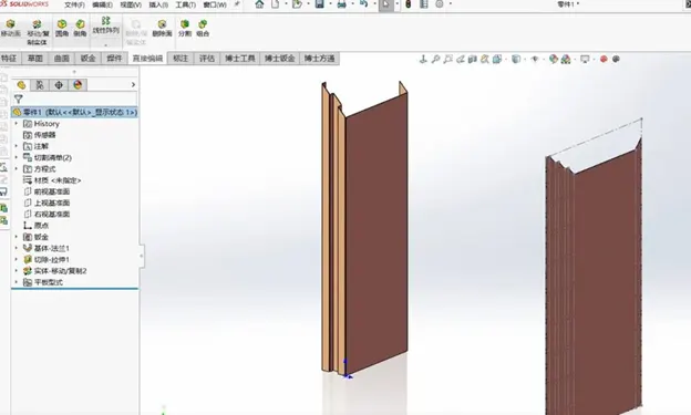
Unfolding sheet metal in SolidWorks involves using the Sheet Metal module. Here’s a step-by-step guide:
Steps to Unfold Sheet Metal in SolidWorks:
Enable Sheet Metal Tools
Go to Tools > Add-Ins.
Check the box for SolidWorks Sheet Metal to enable the Sheet Metal tools.
Import or Create the Part
Open your sheet metal part or create a new one by using the Base Flange/Tab tool in the Sheet Metal toolbar.
Ensure the Part Is Defined as Sheet Metal
If the part is not recognized as sheet metal, you need to convert it:
Use Insert Bends or Convert to Sheet Metal (found in the Sheet Metal toolbar) to define the part as sheet metal.
Specify parameters like material thickness, bend radius, and K-factor.
Access the Flatten Tool
In the Sheet Metal toolbar, locate and click Flatten.
This will unfold all the bends in your part, showing the flat pattern.
Unfold Specific Bends
Use the Unfold tool if you want to unfold specific bends instead of the entire part:
Select Unfold from the Sheet Metal toolbar.
Specify a fixed face (the reference surface).
Choose the bends you want to unfold in the property manager.
Edit the Flat Pattern if Necessary
Add cutouts, holes, or other features as needed in the flat state. These edits will reflect in the folded part.
Refold the Part
After modifications, use the Fold tool to refold the selected bends or click Flatten again to toggle back to the folded view.
Export the Flat Pattern
If you need to export the flat pattern for manufacturing (e.g., to a DXF or DWG file):
Right-click the Flat-Pattern feature in the Feature Tree.
Select Export to DXF/DWG.
Tips
Ensure the part is designed with uniform material thickness throughout.
Define the correct bend allowance or K-factor to ensure accurate flat patterns.
Use Gauge Tables if working with standard sheet metal thicknesses.
Sources of bending coefficients based on the unfolding of sheet metal parts.
According to the use of ‘LVD’ bending machine in production, machine tools and its machine parameters table, in practice, a variety of plate thickness of relatively accurate bending coefficients, in the absence of specific requirements of the sheet metal parts to achieve a rapid expansion, in order to ensure product quality requirements to achieve high efficiency and precision, so as to obtain the sheet metal 90 ° angle of the The bending coefficients for 90° corners of sheet metal are shown in Table 1.
Selection Notes:
1) Table 1 shows the bending coefficients of 90° corners in the sheet metal.
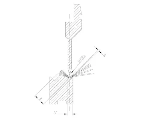
2) Table 1 for the daily production in Belgium according to the production of ‘LVD’ bending parameters, bending machine under the mould as shown in Figure 5.
Parameters summarised from the daily production does have some practical reference, without specifying the angle of the parameters are 90 °.
ss/st- refers to the material is stainless steel and carbon steel; al- refers to the material is aluminium; M- refers to the metric dowel.
Advantages and disadvantages of this bending coefficient parameter
Advantages: In the actual production of regular shape and small R angle of sheet metal parts without special requirements can be achieved quickly and efficiently unfolded, can be directly selected corresponding to the mould and bending coefficient, operability, reducing the traditional method of unfolding the neutral value of the R angle of the tedious calculation work and reduce the human error in the calculation, indirectly reduce costs, suitable for single-piece, complex and multiple pieces of small batch production.
Disadvantage: This table cannot be directly selected for sheet metal parts with special requirements on R angle and shape.
Unfolding examples of applications
In this paper, we have selected a part to unfold the output process, in order to explain the application of bending coefficient in detail.
See Figure 6 for details, the unfolding process is described below.
a. Analyse the drawing before unfolding the study
This sheet metal parts of the material material number for the SUS304 general stainless steel, thickness of 1.00mm, the name of the part for the ‘LIGHTCOVER’ cover, this view using the ‘THIRDANGLEPROJECTION’.
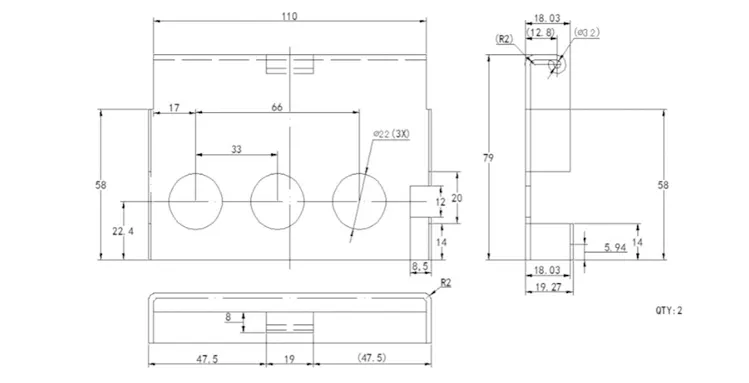
The third corner projection view, all dimensions in millimetres, surface roughness Ra1.6, the graphic is not drawn to scale, notes, unless otherwise specified all the chamfer 0.2 × 45 °, need to be clamped manually circle 3.2mm small round hole moulding.
b, choose bending machine
for the exhibition of the surface of the three-dimensional unfolding of the surface of the choice of similar adaptation of the bending machine die number according to the above situation we can choose the die number for ‘V4’.
Taking into account to be closer to the value of the inner R, so the preferred choice of die number’V4′ 90 ° bending coefficient parameter is 1.5.
Because of the Φ3.2 holes, the first step before unfolding is to use the unfolding calculation method to calculate the length of the unfolded plane, and then make the unfolded plan after subtracting the value of the
bending coefficient by the graphical method, in order to achieve the accuracy of the part when unfolded into a plane .
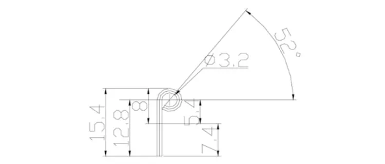
Methods: The schematic sketch is shown in Fig. 7, and the length obtained by the calculation (Eq. 1) is 11.28 mm.
L=π(d+T)-[π(d+T)/360]xα°
L=3.14(3.2+1)-[3.14(3.2+1)/360]×52
L=13.188-1.90
L=11.28(1)
c, calculate value
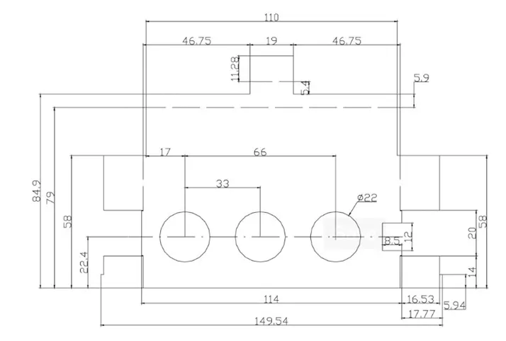
as a whole before the expansion of the graphic surface minus the value of the bending coefficient obtained as shown in the following plan.
d. Output of graphic file after unfolding
From the point of view of CNC sheet metal processing machine tools, the unfolding of irrelevant elements in the drawing mainly includes the size of the label, bending centre line, it is necessary to filter out this part of the elements, and then input into the DXF format, so that you can unfold the programming and cutting of the material.
Summary
Sheet metal processing in the unfolding parameters of the choice of whether or not the accuracy of the direct impact on the success or failure of parts manufacturing, which shows that the bending coefficient in the sheet metal production to expand the importance of the production process and the practicality of the release of the production process.
The correct choice of bending coefficients in the production process also saves a lot of manpower, material resources and time, and significantly improves the quality of the product.
What is the purpose of unfolding sheet metal in manufacturing?
Unfolding is used to create flat patterns of a 3D sheet metal design. These flat patterns guide cutting, bending, and forming processes.
What is a flat pattern in sheet metal design?
A flat pattern is the 2D representation of a sheet metal part that includes all features like cuts and bend lines before it is bent into its final shape.
What software is commonly used for unfolding sheet metal designs?
Popular software includes SolidWorks, AutoCAD, Fusion 360, CATIA, and Inventor, which have dedicated sheet metal tools for unfolding designs.
How do you account for bend allowances during unfolding?
Bend allowances or bend deductions are calculated based on material thickness, bend angle, and tooling radius. These values ensure accurate flat pattern dimensions.
What is K-factor, and why is it important in unfolding sheet metal?
The K-factor is a ratio that represents how much of the sheet thickness is subject to deformation during bending. It helps calculate the accurate unfolded length.
What are common mistakes to avoid during sheet metal unfolding?
- Ignoring material thickness and bend radii.
- Incorrect K-factor or bend allowance settings.
- Overlooking relief cuts for bends or holes near bends.
How do different materials affect the unfolding process?
Materials like aluminum, steel, or copper have different bend properties (elasticity, thickness, and hardness), which affect K-factor, bend allowance, and tooling.
Can sheet metal designs with complex bends or curves be unfolded?
Yes, but advanced CAD tools and techniques are often needed to accurately unfold designs with complex geometries, such as compound curves or non-linear bends.
What are relief cuts, and why are they necessary in unfolding?
Relief cuts prevent tearing or deformation at the bend edges, ensuring smoother bends and an accurate unfolded pattern.

