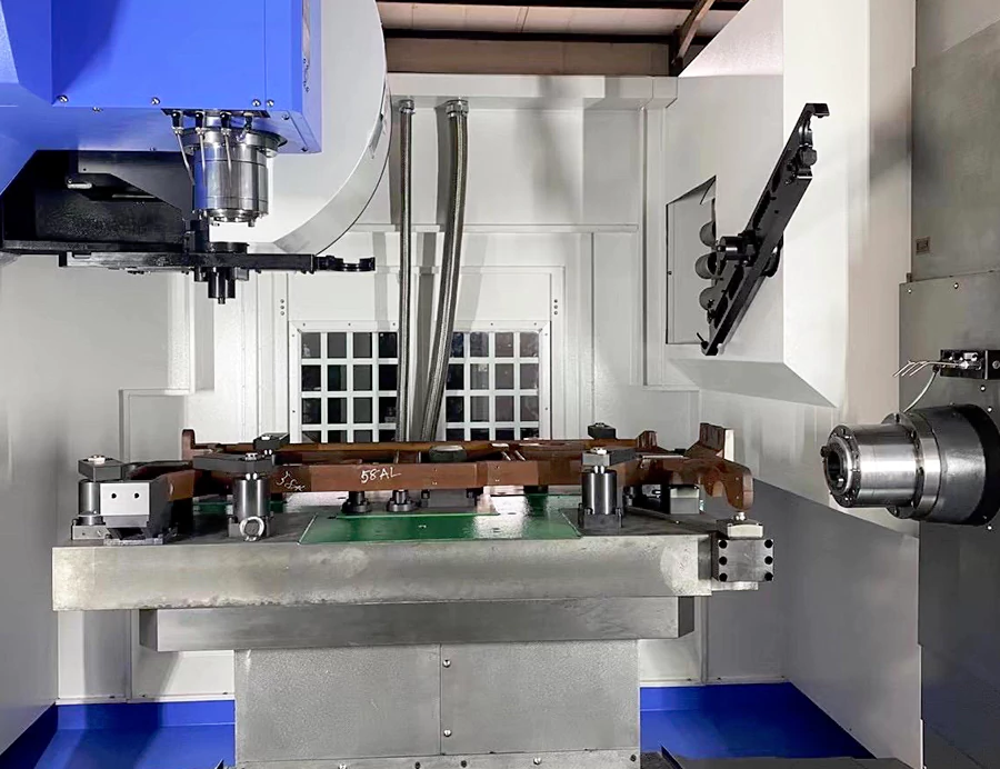
CNC programming technology is a key technology in modern machinery manufacturing, the advantages and disadvantages of CNC programme directly affect the processing efficiency, process stability, processing quality and processing costs.
With the development of the times, the complexity and diversity of products become more and more prominent. More products introduce a variety of curved surface modeling, which challenges traditional manual programming and brings opportunities for the development of automated CNC programming technology.
At the same time, the progress of science and technology promotes the rapid development of engineering application technology.
However, CNC programming is a systematic technology, it is necessary to explore the CNC programming from a systematic point of view to effectively promote the application and development of CNC programming technology.
This paper analyses the composition of CNC programming technology, focuses on the role and role of CAD/CAM technology in CNC programming, and at the same time analyses the role of post-processing technology and key issues, and gives an example study of CNC programming.
System composition and connotation
Considering from a broad perspective, CNC programming technology includes process technology, CAD/CAM technology and CNC machining simulation technology, etc. The system block diagram of CNC programming technology is shown in Fig. 1.

Process technology mainly refers to process planning, tool selection, cutting parameter selection and tool path planning according to the process knowledge;.
CAD technology mainly provides a digital model of the product to generate CNC machining procedures and supply raw data. CAM technology mainly uses the digital model of the product to provide raw data.
CAM Technology for Toolpath Planning and NC Program Generation
- CAM technology uses the machining module of CAM software for toolpath planning and position calculation.
- It generates the NC program based on process knowledge and the product’s CAD model.
- The tool point file, machine structure, and CNC system combine with the program.
- Specific post-processing procedures are applied to generate an NC program in a recognizable format and code.
Verification and Optimization
- The generated NC program is tested in CNC machining simulation systems like VERICUT.
- It simulates the actual machining conditions for inspection and optimization.
- The simulation analyzes the safety and effectiveness of the generated CNC program.
- It helps avoid issues like cutter interference, tool clamping, and workpiece interference.
- The simulation also detects machine tool interference and optimizes cutting speeds along the toolpath.
- Finally, it analyzes the reasonableness of the tool’s trajectory.
If the simulation proves that the NC programme is safe and effective, the actual machining can be carried out, if there are problems with the NC programme, you need to use the CAM software to modify the perfect until safe and effective.
The final generated NC programme to drive the machine tool to perform machining actions, manufacturing the designed product.
CAD / CAM and CNC machining simulation technology
The technology as a typical representative of the field of machinery manufacturing, has been in the aerospace, mould, automotive, general machinery and other industries play a huge role.
Due to the complexity of the product and quality, accuracy requirements, the implementation of modern CNC machining technology is inseparable from the key support of CAM software.
Large commercial CAD / CAM integrated systems such as UG, Proe, MasterCAM, CATIA, Powermill and Cima-tronE, etc. in the product of CNC machining applications have been very common.
Boeing Aircraft Company used CATIA to achieve integrated design and manufacturing without drawings, the successful production of Boeing 777, which is a typical successful application of CAD / CAM technology.
CNC Machining Simulation
Those simulation software like VERICUT, Swan-soft CNCSimulator, and CIMCOEdit can check the correctness of the NC program. The software can optimize and edit the NC program based on certain principles.
This ensures the safety of the actual machining process. It helps avoid issues like interference, collision, and overcutting.
The simulation can eliminate the need for test cuts. It also reduces the waste of raw materials. NC programs can be optimized to ensure machining safety and prevent problems.
These optimizations help avoid interference, collision, and overcutting. We can eliminate test cuts, further reducing raw material waste.
Post-processing techniques
Post-processing refers to converting the tool position source file into NC code. This NC code can be recognized by a specific CNC machine.
Post-processing technology is a key part of CNC programming. It determines if we can generate the correct NC code. The generated NC code must be suitable for the machining machine.
CAD/CAM system software generally provides pre-programmed post-processing procedures. These procedures convert the toolpath source file into NC code. A specific machine tool can identify the NC code.
The software also allows users to personalize the post-processing program. Users can customize the program for a specific machine tool structure and CNC system.
This is done by combining the post-processing module with CAD/CAM software functions. This ensures the post-processing program adapts to a specific machine tool.
Creating a Post-Processing Program
Such as UG software provides two ways to create a post-processing programme, one is the GPM post-processor; second is the UG/POST post-processor.
Graphical post-processor mode, the first need to create machine data files, by the GPM executable file on the tool position source file processing, and ultimately generate CNC programs;
The use of UG/POST post-processing requires event manager files and machine definition files. The post-processing constructor can generate these files.
The UG post-processor uses event management and machine definition file information. It extracts the required information from the toolpath of the part. We then use this information for post-processing to generate CNC programs.
In addition, the system also provides a post-processing constructor that users can customize for specific machine tools and CNC systems.
Users can analyze the motion form of each axis of the machine. This analysis relies on the machine structure and CNC system.
Users can combine programming languages like Matlab and VC++ for post-processing. They can create their own post-processing programs.
These programs convert toolpath source files generated by CAM software. The toolpath files contain commands such as GOTO.
The system converts the toolpath files into NC codes. Specific machine tools can recognize these NC codes.
Case Study
1. CAD model
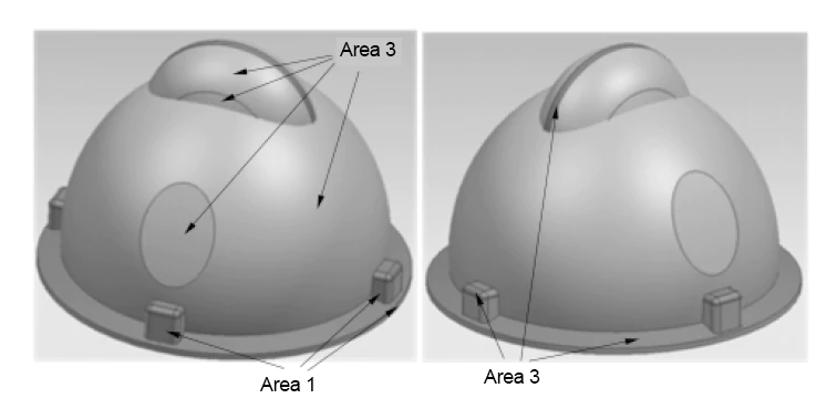
The cube blank has a length, width, and height of 298mm, 298mm, and 210mm, respectively. Figure 2 shows the helmet mould model. The system divides the finishing into 3 areas: area 1 is the steep area, area 2 is the flat area, and area 3 is the transition area.
2. Processing strategy
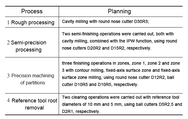
Table 1 shows the machining process planning of helmet mould products, dividing it into roughing, semi-precision processing, precision machining of partitions(zonal finishing), and root-clearing(removal) processing.
The CAM visual toolpath simulation can obtain the IPW (residual blank) after roughing and semi-finishing, as shown in Figure 3 and Figure 4. The roughing residual material is not uniform, and the machining traces are obvious. After semi-finishing, the residual amount becomes more uniform.
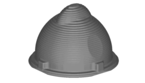
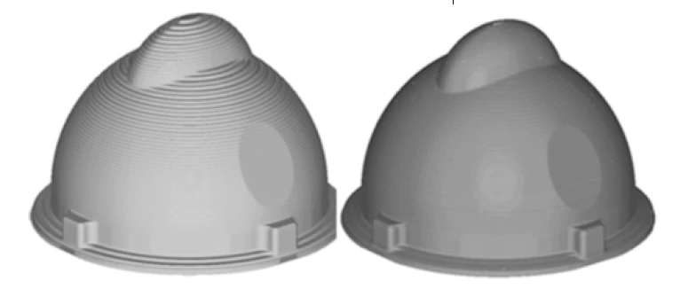
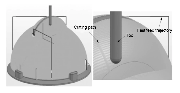
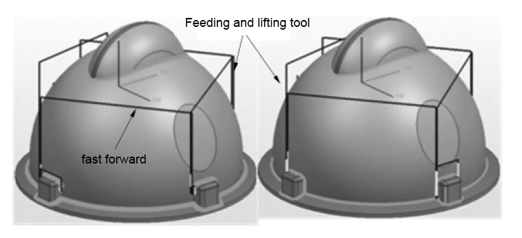
Figure 5 and Figure 6 show the finishing area 3 and the two clear root machining tool trajectories. In area 3, the local toolpath of the finishing process shows that the toolpath direction is difficult to process at the corners with the large-diameter tool. Therefore, the clear root machining tool trajectory mainly generates at the connection of adjacent surfaces.
3. CNC machining simulation, verification and optimisation
CNC machining simulation system VERICUT simulation is mainly divided into APT-CLSF simulation and G-code simulation. Figure 7 shows the process model of the mould after roughing and semi-finishing in the case of CLS simulation, and Figure 8 shows the instantaneous process schematic when finishing area 3.
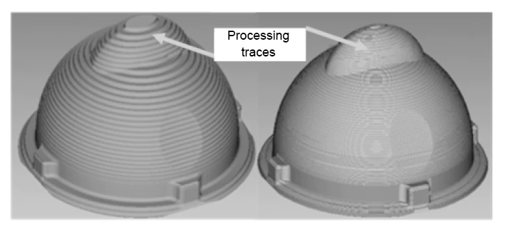
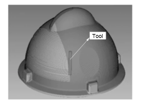
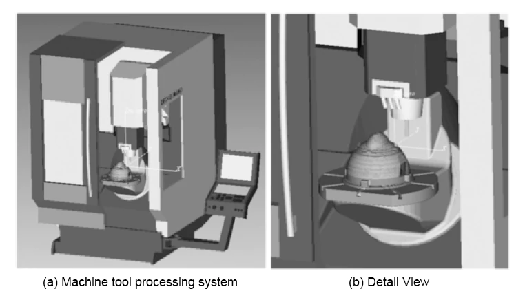
Figure 9 shows the G-code simulation machine simulation view and partial view, the machine view simulation can be close to the real processing environment, which helps to observe the machining process in advance, modify the program in time to avoid errors.
In this case, the combination of constant volume removal rate optimisation and constant chip thickness optimisation is used to optimise roughing, semi-finishing, finishing and root removal.
Roughing and semi-finishing are optimised with constant volume removal rate; finishing and root removal are optimised with a combination of constant chip thickness and constant volume removal rate.
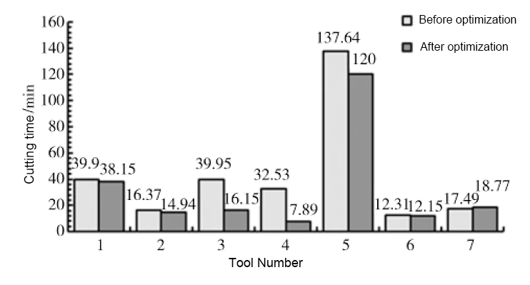
The comparison of tool time before and after optimization is shown in Figure 10.
The total machining time before optimization is 296.19 minutes. The total machining time after optimization is 228.05 minutes. This results in a 23% time savings.
This optimization improves machining efficiency. It ensures a stable volume removal rate. The optimization avoids impact load.
This allows for effective use of the machine tool. It improves tool life and machining process stability. The optimization contributes to the improvement of part machining quality.
Conclusion
The programming is a systematic technology, involving process technology, CAD/CAM technology and CNC machining simulation technology.
Among them, CAM technology is the core of CNC programming, which improves efficiency by making full use of the functions of CAM software.
By combining process knowledge and CAD technology, we can prepare a reasonable and efficient NC program to ensure machining accuracy.
The CNC machining simulation system software simulates, inspects, and optimises the generated NC code for editing to avoid errors.
This can effectively ensure the safety and reasonableness of the NC programme and avoid problems such as interference, collision and overcutting.
At the same time, simulation and optimisation can also protect the machine, tools and workpieces from damage.
Ultimately, these measures can improve the application of CNC programming technology and promote the progress of the manufacturing industry.

