
Rapid prototyping (RPM) is a technology based on the principle of layer-by-layer stacking. By layering the 3D model, discrete points, lines, and surfaces are gradually stacked to form the required parts. Compared with traditional manufacturing methods, RPM does not require special tools, the manufacturing process is simpler, and the speed is much faster, which is also called “free-form manufacturing.”
Since this technology is several times or even dozens of times faster than traditional methods, it has become the core technology of rapid prototyping. RPM has changed the traditional way of making solid models and greatly accelerated the development and updating of products.
RPM technology involves many technical fields, such as CAD, data processing, numerical control, test sensing, laser and other mechanical and electronic technologies, material technology, and computer software technology. It is the organic integration and cross-application of various high-tech technologies.
RPM technology has a good application prospect and practical value. Government departments, enterprises, colleges and universities, and research institutions in the world’s major advanced industrial countries have invested heavily in the development and research of RPM technology. Some colleges and universities and scientific research institutions are also conducting research and development of RPM technology, and have achieved gratifying results, and have been successfully applied to mold manufacturing.
Main methods and principles of RPM technology
The specific implementation process of RPM technology is diverse, Generally, according to the different forming materials used and the treatment methods of the materials, they can be summarized into the following methods, which are introduced as follows:
1. Selective liquid curing method
The selective liquid curing method is to focus the laser on the surface of liquid photocurable material (such as photocurable resin) to cure it according to a pre-set rule, first from point to line and then to surface, to complete the construction of a layer. Then move the lifting platform a distance from the layer’s thickness, and re-cover a layer of liquid material to build another layer. In this way, layers are superimposed to finally become a three-dimensional entity. Typical processes of this method include stereolithography (SL–Stereolithography, as shown in Figure 1), solid grinding Laser lithography laser lithographycuring (SGC-Solid Ground Curing), and laser lithography (LS–Light Sculpting).

Fig 1. SL (stereolithography) process schematic diagram
2. Layer addition method
The layer addition method uses a laser or a tool to cut the foil material to obtain a layer of the model. Specifically, the process border and the edge contour of the prototype are cut out first, and then the material that does not belong to the prototype is cut into a grid. By continuously moving the lifting platform and giving the foil material, new layers can be cut and bonded to the previous layers. In this way, a three-dimensional solid model can be formed by stacking layers.
Finally, the small pieces of material grid that do not belong to the prototype are removed to obtain the required three-dimensional solid model. There are many kinds of foil materials used in the layer addition method, such as coated paper (paper coated with an adhesive coating) coated with ceramic, metal foil, or other material-based foils. The typical process for slice addition is layered solid manufacturing (LOM–Laminated Object Manufacturing), as shown in Figure 2.

Fig2. LOM (Layered Entity Manufacturing) process schematic diagram
3. Selective powder sintering/bonding method
The selective powder sintering/bonding method uses special powder to form layers with specific density and flatness. The powder is selectively melted or bonded to create an integral layer. New powder is then spread over the formed layer, compacted, and sintered or bonded to form the next layer, fusing with the previous one. This process continues layer by layer to create a 3D object.
Powder materials include non-metallic options like wax, polycarbonate, and washed sand, as well as metal powders such as iron, cobalt, chromium, and their alloys. Typical processes include Selective Laser Sintering (SLS) and 3D Printing (3DP), as shown in Figures 3 and 4.

Fig3. SLS (Selective Laser Sintering) process schematic diagram

Fig 4. 3DP (three-dimensional printing) process principle diagram
4. Melt extrusion molding method
The melt extrusion molding method is to melt the hot melt material by heating, then extrude and spray it out to accumulate a forming layer, and then form the next layer in the same way and fuse it with the previous layer. In this way, a three-dimensional solid model is finally formed by stacking layers. Hot melt materials include ABS, nylon wax, etc. The typical process of melt extrusion molding is fused deposition modeling (FDM–Fused Deposition Modeling), as shown in Figure 5.

Fig 5. Schematic diagram of the melt extrusion molding (FDM) method
5. Inkjet printing method
Inkjet printing is to melt the solid material, and then use the principle of inkjet printing to spray it out in an orderly manner, stacking one layer after another to form a three-dimensional entity. The typical process for inkjet printing is Ink-Jet Printing, as shown in Figure 6.

Fig 6. Inkjet printing principle
6. Digital light processing
Digital light processing (DLP) is mainly used for 3D printing of photocurable resins. Its working principle is to project the 2D image generated by slicing the 3D model onto the photosensitive resin layer by layer through a digital projector. The resin is quickly cured under light to form a solid structure. During the printing process, the printing platform is immersed in the resin pool. After each layer of curing is completed, the platform is slightly lifted and covered with a new layer of resin again. The curing is repeated until the model is completed, as shown in Figure 7.

Fig 7. Digital light processing schematic
Table 1. Comparison table of five rapid prototyping methods

The development trend of RPM technology
RPM technology is of great significance in the manufacturing industry. This manufacturing model has developed rapidly since its inception. RPM has undergone fundamental changes and improvements in manufacturing goals, manufacturing capabilities, and manufacturing technologies compared to the past. The development prospects of this technology are very promising, and the technology itself will continue to improve.
1. Manufacturing goals develop relatively independently
From a manufacturing perspective, RPM technology supports rapid production of concept prototypes, functional test prototypes, molds, and parts.
Concept design prototypes have fast molding, small equipment, reliable operation, and low noise. Examples include the 3DSYSTEM Actua2100 and EOS DESKTOP200 systems.
Functional test prototypes must meet strength, rigidity, temperature, corrosion resistance, and precision requirements. This demands research into special materials.
Quick model prototypes require specific materials and affect manufacturing modes, like 3DSYSTEM’s QuickCast.
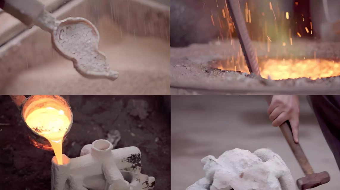
RPM technology is also widely used for manufacturing molds, such as vacuum injection, lost wax, sand casting, and lost foam molds.
Functional rapid parts remain a key challenge and research focus in RPM.

Fig 8. Lost Wax Casting Mold

Fig 9. Sand casting mold
Rapid concept manufacturing and rapid tooling manufacturing both have huge market and technical feasibility and will become the focus of research and commercialization.
Due to the large differences in their characteristics, both will tend to develop relatively independently.
Rapid testing has limited use and unclear characteristics, so it won’t develop as an independent direction. It will remain part of rapid concept manufacturing.
Rapid functional parts manufacturing will be a key direction for RPM technology development. However, it is complex and will likely stay in the research phase for a long time.

Fig 10. Relationship and difference
2. Large-scale Manufacturing and Micro-Manufacturing
2.1Growth of Prototype Manufacturing
Analysis of major companies’ product lines shows that prototype sizes are increasing. Due to challenges in large mold production and RPM’s advantages in mold manufacturing, a significant portion of the RPM market will likely shift to large prototype manufacturing in the future.
2.2Applications in the Automotive Industry
The rapid development of the automotive industry has increased the use of large-scale rapid prototyping. This technology is mainly used for manufacturing automotive molds, which require high speed and accuracy.
As vehicle model turnover speeds up, the demand for faster, more precise automotive cover molds grows. Large-scale rapid manufacturing technology perfectly meets these needs.
2.3Micro-Manufacturing with RPM
In contrast, RPM has also entered micro-manufacturing. One key area is microlithography, particularly in SL technology, which produces micron-sized parts. The laser spot diameter can reach 5μm, and the prototype remains stationary during the process.
The laser beam focuses precisely on the prototype through a transparent plate. The XY scanning stop accuracy is 0.25μm, and the Z stop accuracy is 1μm. This technology can produce parts as small as 5μm x 5μm x 3μm, such as venous valves and integrated circuit components.
2.4The Rise of Desktop Manufacturing Systems
Desktop manufacturing systems are gaining popularity in RPM product development. They are increasingly used as peripherals for CAD systems to output 3D graphics.
RPM systems need to be compact and efficient, allowing them to operate in office environments without disrupting CAD workflows.
Commercial RPM systems are typically large, requiring specific environmental conditions and specialized operators. In contrast, desktop systems are compact, easy to operate and maintain, generate less noise and pollution, and have fewer environmental requirements.
While they offer faster production speeds, they have slightly lower accuracy. Companies like Stratasys and SandersPrototype in the U.S. have launched affordable desktop systems, such as Genisys3DPrinter and ModelMaker. These systems have quickly gained market traction, highlighting the enormous potential of desktop manufacturing.

Fig 11. RPM technology distribution diagram
3. Strive for excellence in manufacturing technology
The strategy of rapid prototyping (RPM) companies is not only to launch new models but also to continuously improve existing processes, equipment, materials, software, and electromechanical systems. Their goal is to achieve faster production speed, higher precision, and better reliability, or to find a balance between these goals. This trend will continue.
Modern manufacturing technology is developing in a highly integrated direction. It combines CAD (computer-aided design), data processing, numerical control, test sensing, laser, and other mechanical and electronic technologies, as well as material and software technologies to form a new way of manufacturing.
At the same time, modern manufacturing is becoming more and more flexible. The biggest advantage of RPM technology is its high flexibility, and it no longer relies on special tools.
Under computer management and control, RPM can manufacture parts of any complex shape. It integrates programmable, reconfigurable, and continuously variable production equipment with information management into one system, so the production cost is independent of the production batch. When the shape, requirements, or production volume of a part changes, there is no need to redesign or manufacture tools. Just modify the CAD model and adjust the parameters to produce a new part.

Fig 12. The integration of various technologies
4. Installation of peripherals and intelligent operation
RPM technology is evolving toward “directly driving CAD models to quickly manufacture complex 3D models.” Some RPM equipment in the U.S. is becoming simpler and easier to use, like computer peripherals. In the future, these systems will be easy to install and operate, allowing ordinary users to get started without specialized technicians. Operations will also become more intelligent.
Currently, RPM manufacturing involves many complex decisions, such as support structure design, scanning method selection, part arrangement, large part segmentation, and process parameter settings. These tasks usually require professionals. However, with advancements in artificial intelligence and a deeper understanding of RPM technology, the intelligence of RPM equipment will soon enable everyday users to operate it with ease.
5. RPM industry standardization and integration with product manufacturing system
5.1Lack of Industry Standards
Various RPM process methods have developed independently, resulting in a lack of uniform standards. This is an inevitable aspect of new technology development. In fact, the absence of standards has fueled RPM’s growth and innovation.
However, as RPM matures into a full-fledged industry, the establishment of reasonable standards is essential. Without them, the promotion and application of RPM could be hindered. Currently, the de facto standard in the RPM industry is the STL file format for product data exchange.
However, many also use other file types, such as CLI, HPGL, and DXF, making standardization an important issue. In addition, the standardization of materials and equipment models is likely to continue advancing.
5.2Real-World Examples of RPM Impact
According to the Rapid Prototyping Report (1996, Issue 11), Whirlpool successfully used FDM equipment to provide rapid feedback design for the lighting unit of a refrigerator’s refrigeration room. With FDM technology, Whirlpool reduced the time from redesign to mold-making by about one year, revising the design five times more than with manual methods. This redesign saved the company an estimated $650,000.
Similarly, a U.S. golf club design company, which previously used brass to make models, found the process time-consuming and only produced three design iterations. By adopting a LOM-1015 RPM machine, they produced 90 models in one year. This allowed for quicker design iterations at a lower cost, improving decision-making efficiency.
5.3Integrating RPM with Product Manufacturing Systems
The relationship between RPM and the broader product manufacturing system is crucial. Key questions include: how to describe RPM data in the STEP model, and how to integrate RPM into rapid product development systems.
These challenges involve two core aspects:
(1)Data Representation and Integration
Developing standardized ways to represent RPM data in systems like STEP.
(2) RPM’s Role in Rapid Development
Understanding how RPM technology fits into and enhances the rapid product development process.
5.4 How to describe RPM data in the STEP model
(1) Geometric data description
3D model data: The core data used by RPM is usually a 3D model that describes the shape and structure of the product. The STEP format allows complete geometric information storage and supports 3D printing of RPM.
Feature data: The STEP model can save the features in the design (such as holes, slots, etc.), which helps the processing process of RPM technology.
(2) Material information
The properties of the manufacturing material can be described in the STEP file. The material information (such as density, melting point, hardness, etc.) directly affects the process method selected in the RPM process (such as laser sintering or melt extrusion).
(3) Process parameters
Manufacturing process data: STEP scalability allows the storage of process data related to the RPM process, such as layer thickness, printing speed, laser power, etc., which is very important in executing the manufacturing process.
(4) Assembly information
The multi-part assembly of RPM can be managed through STEP model data. STEP supports complete assembly hierarchical structure description, which facilitates simulation and adjustment in the production process of complex parts.
(5) Manufacturability Check
During the design phase, STEP can include analysis data related to manufacturability to ensure that the designed parts are suitable for manufacturing through the RPM process.
5.5 How to develop and apply RPM in a rapid product development system
(1) Shorten the design verification cycle
RPM technology allows companies to generate physical prototypes in a few days or even hours. Product design teams can quickly test, verify, and modify designs, greatly shortening the traditional verification cycle.
(2) Concurrent Engineering
By integrating with STEP-data models and CAD systems, RPM can perform multiple design iterations in parallel in the early stages of development, avoiding the traditional linear development process. This allows different stages of product development to proceed simultaneously, further accelerating product launch.
(3) Prototype testing and functional verification
In the rapid product development system, RPM can produce functional prototypes, not just appearance models. This means that the product can pass real functional tests before entering mass production, reducing the risk of design defects.
(4) Agile manufacturing and small-batch production
RPM technology also supports small batch production for market testing and personalized customization, which is particularly suitable for the initial promotion of innovative products. In an agile manufacturing environment, RPM enables companies to quickly adjust product designs based on market feedback.
(5) Collaborative design and cross-team cooperation
In the modern development system, the combination of the STEP model and RPM facilitates global collaborative design. Designers, engineers, and manufacturing teams can share data and update design progress in real time, thereby optimizing the production process and reducing the error rate.
(6) Cost-effectiveness
By reducing the intermediate links such as design modification, tooling manufacturing, and mold production, RPM makes the development process more economical, especially in the early development stage.
Conclusion
With the continuous advancement of rapid prototyping technology, it has become an indispensable part of modern manufacturing. From design to production, this technology has brought huge efficiency improvements to all walks of life.
Different RPM technical methods provide diverse options for different needs and application areas, promoting the development of mold manufacturing and other related industries. Looking to the future, rapid prototyping technology will continue to develop in the direction of higher precision, larger scale,e, and wider application, helping the manufacturing industry to usher in a more intelligent and flexible era.

