
Beam parts bear the aircraft fuselage load and include features like edges, slot cavities, bars, and mitigation holes. Most parts have thin walls, which makes them prone to machining issues and deformation.
Issues with Traditional Clamping Methods
Milling beam parts often require assembly fixtures for clamping and fixing. The use of bolts and pressure plates around the parts can be time-consuming and cumbersome. Finding the right clamping method is labor-intensive, and the setup process can be lengthy. Additionally, the milling force is not always uniform, leading to deformation and a high scrap rate, especially during the finishing process.
The Problem with Double-Sided Beam Parts
Double-sided beam parts lack external support and have low rigidity. During machining, if the cutting force is too large or resonance occurs, it can cause vibrations in the belly plate. This leads to quality issues, particularly in the finishing stage.
Limitations of Traditional Clamping and Positioning
Traditional platen clamping methods suffer from low productivity, inconsistent processing quality, and failure to meet process requirements. These limitations highlight the need for a new, more efficient CNC machining process.
Solution: Fast Positioning and Clamping Fixture Design
To address the defects of traditional methods, this paper proposes a fast positioning and clamping milling fixture based on vacuum adsorption technology. This fixture is designed to improve clamping efficiency and reduce machining deformation during the finish machining of beam parts.
How the Fast Clamping Fixture Works
The fast clamping solution uses the vacuum adsorption principle. Multiple vacuum adsorption blocks are used to position the parts and provide support. This system ensures uniform clamping force, reducing cutting vibrations caused by low rigidity. A pressure plate further minimizes machining deformation, improving both clamping efficiency and positioning accuracy.
Structure and process of beam parts
Beam parts of the aircraft fuselage are a key part of the modern aircraft, generally used die forging parts machining manufacturing, belong to the more difficult to process large parts. The shape of the beam is mostly a straight line along the longitudinal direction of the fuselage, the internal design of many cavity features, the cavity is generally a flat-bottomed groove with a closed boundary profile, which can ensure the overall mechanical properties of the component while removing excess material, to achieve the lightweight design requirements of the aircraft. To improve structural efficiency, the cross-section shapes of beam structures include U-shape (single-sided beams) and I-shape (double-sided beams), etc. Fig. 1 shows the cross-section shapes of typical double-sided beam parts.

Aircraft beam parts are thin-walled components. They typically use high-strength, high-modulus materials such as titanium, aluminum alloys, or alloy steel. Due to its special structural characteristics and material properties, there are large differences resulting in a large coefficient of difficulty in processing, technical requirements, and assembly requirements.
Beam parts are generally larger external dimensions, double-sided beams on both sides of the distribution of several groove cavities, parts of the web, bar, edge of the thin thickness of the strip, the cross-section relative to the outer dimensions of the smaller, rigid, easy to cut vibration, machining processability is poor in the machining process is very easy to produce deformation, the size is not easy to ensure that affects the machining quality of the parts, the material removal rate of the large, especially in the finishing stage of the requirements of the process equipment Higher.
Fixture structure design
Statistics show that the fixture closely correlates with the workpiece. Clamping and fixture accuracy cause 20% to 60% of machining errors, affecting both positioning and stiffness. Therefore, the structural design and optimization of the fixture is very important. By reasonably arranging the clamping elements and suitable clamping force, the fixture can realize the positioning, constraint, and support of the workpiece during the machining process to ensure the accurate positioning and firm clamping of the workpiece. Since the vacuum adsorption fixture realizes the vacuum clamping and positioning by the sealing elements, the sealing structure is the focus and key part of the design of the vacuum adsorption fixture.
In addition, in the fixture design process, to ensure the strength and rigidity of the fixture, and according to the requirements of the CNC equipment, allowing the tool to reach as many machining surfaces as possible, or even all machining surfaces, to reduce the machine’s downtime as well as fixtures, tools, workpiece system adjustment time.
1. Working Principle
A vacuum clamping fixture works by using a vacuum pump to create negative pressure in the cavity between the part and the fixture. This generates a clamping force that tightly holds the part in place. The system doesn’t damage the clamping surface or require workpiece adjustments. It also reduces deformation caused by uneven clamping, improving machining accuracy and surface finish.
The vacuum pump controls the fixture’s clamping, with several positioning blocks ensuring accuracy. The pump generates the clamping force, and turning it on and off adjusts the fixture’s grip on the part.
2. Design program
Work-type beam parts require double-sided milling, demanding high precision during the machining process. To meet precision requirements, we minimize deformation and aim to complete as many machining processes as possible in a single clamping.
The fixture clamps using vacuum adsorption.
The positioning block is bolted to the fixture’s positioning plate at the bottom, while the top contacts the part.
Vacuum adsorption applies uniform forces across the part’s inner cavity, reducing deformation.
Due to the increased contact area, under the condition of a certain pressure of the air pump, it can prevent the parts from vibration in the process of machining caused by the problem of low machining accuracy. In the use of fixtures, the separate design of the live block adapts to the different cavity shapes of the parts, thus maximizing the expansion of the use of fixtures. Fig. 2 shows the composition of the milling fixture.
The fixture base consists of the base plate, support plate, and welded reinforcement, providing support and fixation. Countersunk holes on the base plate secure the fixture to the machine table, while four holes accommodate lifting bolts. To reduce weight, the support plate features oblate relief holes, and threaded holes on the top surface secure the locating plate, as shown in Fig. 2.

The positioning plate is a flat plate that matches the part’s external dimensions and structural features. It supports and secures vacuum positioning blocks and parts.
The steps are designed to match the part’s rim height, preventing interference with the positioning plate.
The plate has pin holes and threaded holes to position the vacuum blocks precisely. Threaded holes also secure the plate to the fixture base.
Pads adjust the vacuum blocks’ height, ensuring they align at the same top surface height.
3. Structural Design of Vacuum Positioning Block
The vacuum positioning block is a key component of the milling fixture and is based on the structural characteristics of the beam parts designed for the movable positioning unit, its number, and external dimensions by the number of parts of the slot cavity and the size of the internal shape to determine the structure of the two are generally similar to the dimensions of the external dimensions of the different (see Fig 3).

(1)Upper Surface Design: Effective Vacuum Adsorption Area
The upper surface of the vacuum positioning block is the effective area of the vacuum adsorption work, to ensure the adsorption effect, the vacuum positioning block of the machining accuracy and surface roughness requirements are high.
(2)Sealing Mechanism for Pneumatic Clamping
Pneumatic clamping requires a strong seal. The vacuum positioning block’s upper surface has a sealing groove to hold rubber strips. This design seals the vacuum cavity, preventing air leakage during clamping and machining. The sealing groove profile fits the part’s slot cavity, 3 to 5mm smaller, ensuring full coverage by the belly plate.
(3)Groove Cavity and Clearance Design
The vacuum positioning block fits the groove cavity, leaving a 2-3mm clearance. Fig. 4 shows its typical structure. In Fig. 4a, the vacuum positioning block includes vacuum extraction holes and bolt holes, serving to extract vacuum and fix parts. The block also has vacuum extraction slots and sealing grooves on its top surface.
(4)Vacuum Pumping Groove and Hole Distribution
The vacuum pumping groove uniform and vertical cross-distribution, and the adsorption of the slot cavity contour to adapt to the slot width of 1mm, the depth of the slot 0.5mm, vacuum pumping groove, and vacuum pumping holes through the formation of the vacuum channel.

(5)Sealing Groove Specifications
The sealing groove follows a circular shape along the periphery, with its width based on the sealing strip specifications. The milling jig uses a round sealing strip (ϕ6mm) to ensure reliable sealing. The groove’s cross-section is drum-shaped, with a diameter of ϕ6mm. A drum milling cutter processes the groove to a depth of 5mm, positioning the groove’s centerline 5.5mm from the edge.
(6)Bottom Surface Design: Pin Holes and Threaded Holes
The vacuum positioning block’s bottom surface has two pin holes for positioning. Typically, six threaded blind holes are located on the bottom, based on the block’s shape and size (see Fig. 4b). These holes are fitted with threaded bushings (see Fig. 4c), and the block is secured to the positioning plate with bolts. Its connection is shown in Fig. 5.

positioning process and applications
1. Fixture Assembly and Positioning
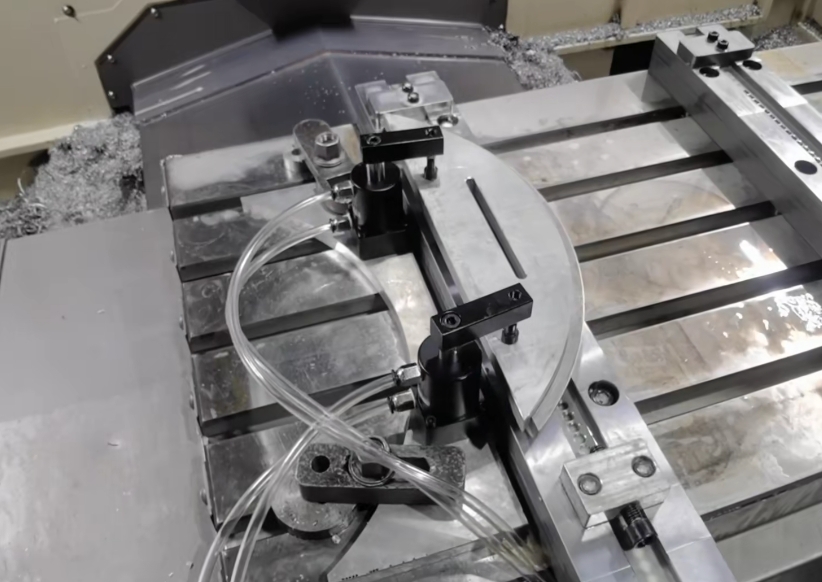
End stops, side stops, and platens hold and assist in pressing the part, as shown in Fig. 6. The process clamps and positions the part as follows:
(1)Assemble the Fixture Components
Assemble the fixture components and place the fixture on the machine table using a lifting device. The datum surface and two datum holes are pre-set on the sides and ends of the positioning plate. Using the percentage table and the holes on one side, we find the correct clamping method. This ensures parallelism and perpendicularity with the machine tool table. Finally, bolts fix the positioning plate to the machine tool table.
(2)Connect the Vacuum System
Connect the vacuum holes of all vacuum positioning blocks to the vacuum system through the vacuum interface and connecting pipe.
2. Placing the Parts
(1)Prepare the Fixture
Embed ϕ6mm rubber strips into the ring sealing grooves on the upper surface of all vacuum positioning blocks. Place the semi-finished parts on the fixture so that all the grooves on the first side correspond to the vacuum positioning blocks one by one. Ensure the web surface of the parts is in full contact with the upper surface of the vacuum positioning blocks, as shown in Fig. 6.

(2)Activate the Vacuum System
Turn on the vacuum pump to achieve rapid positioning, clamping, and processing of the part. The workpiece receives a downward adsorption force, ensuring the web surface and the vacuum block’s upper surface adhere for secure positioning and clamping.
(3)Secure the Workpiece
Bolts fix the top surface, while pressure plates clamp both sides to prevent the adsorption clamping from affecting the part during processing.
3. Machining Process
Execute the numerical control program to complete machining tasks, including:
Refining the height of the edge strip
Shaping the part’s contours
Machining the inner profile of the groove cavity and web
Drilling holes
4. Completion and Fixture Removal
After completing the workpiece processing, close the vacuum system. At this point, the suction force is 0. Remove the two sides of the auxiliary clamping pressure plate and lift out the processed workpiece in preparation for the next machining process or to end the processing.
5. Benefits and Applications
The fixture successfully finishes double-sided beam parts. The operation is simple, with quick clamping, reliable positioning, and high productivity. The processing deformation is small, the thickness is uniform, and the quality meets the requirements.
The use of vacuum adsorption fixtures solves the problems of low machining efficiency and finishing deformation in beam parts. By fixing the parts securely, the fixtures prevent interference during the machining process, allowing for multi-process machining with enhanced accuracy and efficiency.
Conclusion
This paper analyzes the structural characteristics and process requirements of aircraft beam parts, for the CNC machining of beam parts to design a double-sided beam parts finishing vacuum adsorption milling fixture structure, put forward a vacuum adsorption, fast clamping program.
The milling fixture adopts the vacuum adsorption system to fix the parts, is easy to operate, has reliable positioning, and no clamping stress deformation, in practical application effectively improves the parts in the milling process due to uneven clamping force caused by the processing of deformation problems, to achieve accurate positioning of the workpiece and fast clamping, improve the clamping efficiency, the machining accuracy of the parts and the surface roughness of the parts, the machining of thin-walled parts have reference significance.
In the fixture design process, the vacuum positioning block can change the shape design according to different machining needs, so that the milling fixture is both personalized and universal, and can be widely used in mass production of double-sided beam parts. The use of vacuum positioning blocks to support the web increases the rigidity of the processing system and uniformly distributes the clamping force, resulting in improved machining reliability.

