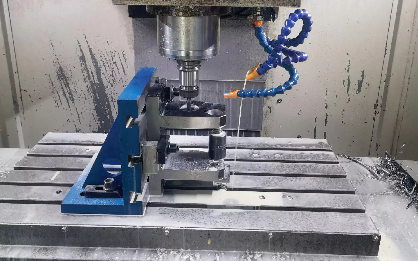
At present, three-axis CNC milling machines are among the most used CNC machine tools worldwide, and the industry welcomes their high price-performance ratio.
However, many details and process arrangements also need attention in its daily processing. Here is an example to give you a deep impression of its use.
The customer has an air volume adjustment handwheel, which is used to adjust the air conditioner in the sleeper compartment of the train.
However, the product has been discontinued, and we need to re-process a batch for him.
From his hands’ physical point of view, the product is not complicated. However, in the case of a high cost-efficiency ratio, we need to consider how it is processed more.
The premise is that one is to meet customer demand, and the other is to create revenue for the factory.
Analysis of processing difficulties
Figure 1 shows the sectional view of the air volume adjustment handwheel.
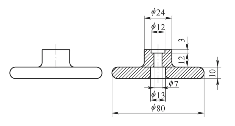
The handwheel is produced and processed using four, five-axis milling and turning composite machining technology, which is fast, convenient, and easy to operate.
Still, the cost of equipment operation is very high. This requires careful consideration, and thus, a separate 3-axis CNC milling machine is needed to process the air volume adjustment handwheel.
(1) Design fixture
The front and back sides of the airflow regulator handwheel need to be milled separately to ensure its integrity and flatness.
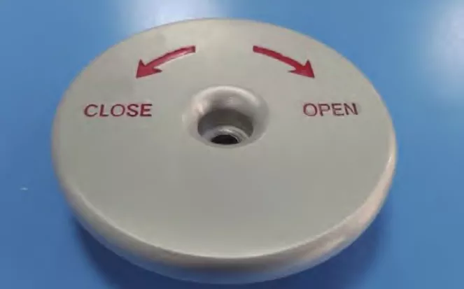
Figure 2 shows the appearance of the reverse side of the handwheel.
After machining the contour of the reverse side of the handwheel, the material needs to be turned over and fixed.
This is done before machining the front side to ensure the flatness of the machined handwheel plane and the parallelism of the upper and lower two horizontal end surfaces.
As Figure 2 shows, the transition area in the middle of the handwheel is chamfered and has a smooth surface, which is not conducive to clamping and fixing in a milling machine vise.
Forced clamping and milling can result in the material tilting and shifting during the milling process.
This will prevent the restoration of the original handwheel’s form ideally and may even cause the machined material to be scrapped.
For the above reasons, designing a specific handwheel clamping device is one of the machining process’s difficulties.

(2) Milling steps:
It is also crucial to determine the steps of the milling process based on the technical requirements of the independent milling process.
The milling process needs to take into account the structural characteristics of the airflow regulator handwheel, and combined with the conditions of the milling machine on site for the design of the milling steps, it is required to be reasonable and implementable.
(3) The handwheel needs to be secondarily positioned in the front and back of the milling process.
When the reverse side of the regulator handwheel processing is completed, the need to turn the workpiece after this action is completed will inevitably lead to the workpiece and the primary placement of the offset position.
Figure 3 shows the chamfered front side of the handwheel. The positional offset will deform the handwheel’s overall shape in the workpiece’s subsequent milling process, increasing the difficulty of the secondary positioning.
Processing
Aluminum alloy is chosen as the processing material for handwheel for the following reasons:
① The cutting processing methods of aluminum alloy include drilling, milling, turning, boring and sawing, etc., of which the most widely used are turning and milling.
② The cutting and machinability of aluminum alloy are similar to copper alloy.
③ The hardness and strength of aluminum alloy are relatively low, plasticity is small, the tool wear is minor, and the thermal conductivity is high, so the cutting temperature is low.
Aluminum alloy cutting and processing are better. It belongs to the easy-to-machine materials, suitable for higher cutting speeds.
The machining steps of the air volume adjustment handwheel are as follows.
(1) Reverse machining
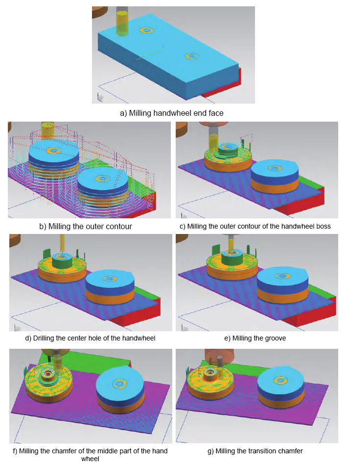
The reverse side of the handwheel milling processing steps is shown in Figure 4.
Prepare the CNC program on the machining center and clamp the aluminum block on the milling machine’s vise.
① Apply φ 20mm three-flute milling cutter to mill the aluminum plane.
The spindle speed is 3000r/min, and the feed speed is 1250mm/min.
This step ensures the surface of the aluminum block is flat and makes the height flush with the highest end of the opposite side of the handwheel, as shown in Fig. 4a.
② Machining contour
The excess material on the outside of the handwheel contour is milled and removed, as shown in Fig. 4b, to mill out the external contour.
③ Milling the outer contour
Use φ 16mm three-flute milling cutter to mill the excess metal from the outer contour on the handwheel’s cam platform.
As shown in Fig. 4c, the spindle speed is 3000r/min, and the feed speed is 1250mm/min.
The step should leave part of the allowance for the chamfering cut of the middle part of the handwheel.
④ Punch the hole
Use φ 7mm drill cutter to punch the hole in the centre of the handwheel, the spindle speed is 819r/min, the feed speed is 250mm/min, as shown in Fig. 4d.
⑤ Process the groove
To mill and process the groove, use φ 8mm four-flute milling cutter; the spindle speed is 2000r/min, and the feed speed is 1250mm/min, as shown in Fig. 4e.
⑥ Milling the middle chamfer
Milling the chamfer in the middle part of the handwheel is done with a φ16mm three-flute milling cutter.
The spindle speed is 3000r/min, and the feed speed is 1250mm/min. Milling is carried out to the edge of the proximity chamfer, as shown in Fig. 4f.
⑦ Milling transition chamfer
As shown in Fig. 4g, replace the φ 10mm two-flute ball end milling cutter to process the transition chamfer.
⑧ Machining the upper arc chamfer
Use a φ 8mm two-flute internal R milling cutter with a spindle speed of 3000r/min and a feed speed of 1250mm/min to machine the upper arc chamfer of the gripping part on the opposite side of the handwheel.
(2) Frontal machining
Frontal machining requires using jigs to fix the handwheel according to the characteristics of the air volume adjustment handwheel.
The design of the fixed fixture shown in Figure 5 avoids the middle of the chamfer. The handwheel is processed to do the support, and fixed processing is required.

After turning the handwheel, the tool must be positioned twice to ensure the milling process. A hole is left in the center of the handwheel after turning.
According to the characteristics of this position, a φ7mm drilling cutter is used for positioning.
The position of the drilling cutter is adjusted continuously to ensure that the cutter can rotate normally at this position and complete the secondary positioning.
Fig. 6 shows the machining steps for the front side of the handwheel. As shown in Fig. 6a, 6b, and 6c, a 4-flute milling cutter and internal R cutter are applied to process the handwheel, milling the final shape.
Machining the marking with an engraving cutter is done to complete the machining of the handwheel, as shown in Figs. 6d and 6e.
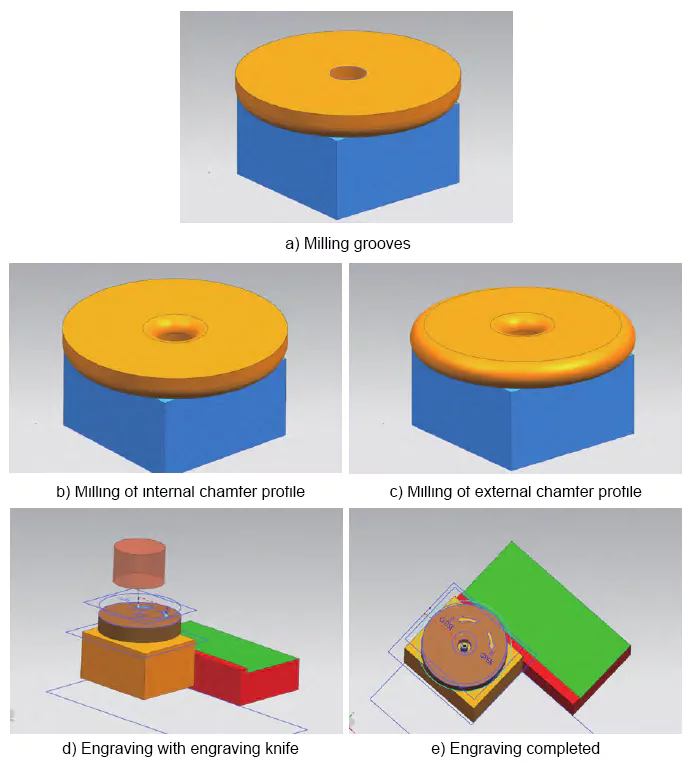
Figure 6 Handwheel front processing steps
Error analysis and application verification
(1) Error analysis
The appearance of the milled air volume adjustment handwheel is almost the same as that of the original.
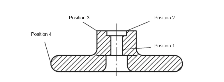
Several handwheel positions are marked with partitions, as shown in Fig. 7.
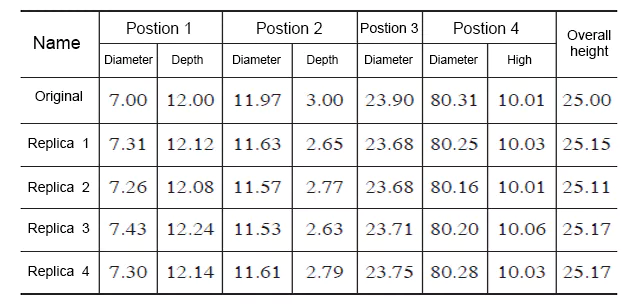
Table 1 shows the dimensions of the original handwheel and the four imitation handwheels.
Comparing them, it can be seen that the dimensional error of each part of the milled handwheel is controlled within 0.5mm, which is a minimal error.
(2) Application verification
The airflow-regulating handwheel is applied to control the air conditioning airflow machine.
The application test is carried out on several handwheels that have been milled and processed.
The results show that the handwheel, milled by applying the above method, can control the regular operation of the air conditioning airflow machine.
Its performance is the same as that of the original.
This method solves the problem of using the milling machine alone to process the air volume adjustment handwheel, and the field test shows that it is highly feasible and implementable.
Conclusion
Using three-dimensional modeling and CNC machining technology, 1:1 modeling of the original handwheel generates CNC machining procedures.
The aluminum alloy block is machined into a usable handwheel using CNC machine tools.
This allows the damaged or lost handwheel to be replaced during the overhaul operation. It ensures that the overhaul operation complies with the standards.
Its three-axis CNC milling machine is used on-site, imitating this accessory and achieving success. The original handwheel is a three-dimensional five-axis CNC machining in one piece.
The site uses a flip clamping fixture and NextGeneration technology. Flipping CAM positioning achieves three-axis CNC milling machine processing, replacing the five-axis milling and turning composite processing effect.
The process allows for the reproduction of discontinued parts at a very low cost. It effectively solves the problem of complex spare parts procurement for old imported buses.

