
Multifunctional compound machine tools(Also called Multitasking machines) integrate multiple processing functions, significantly improving processing efficiency and accuracy, and have become indispensable equipment in modern manufacturing.
With the continuous advancement of technology, the functions and application areas of this type of machine tools continue to expand, providing innovative solutions for efficient processing of complex workpieces. This article will explore the current development status of multi-function compound machine tools and their importance in the manufacturing industry.
Author: LIU Feng
The development of multi-axis turning-milling composite machining technology began in the 1990s as a response to the modern manufacturing industry’s need for diverse, small-batch, and customized production. This advanced machining technology integrates traditional mechanical design and precision manufacturing techniques with modern advanced control technologies, precision measurement technologies, and CAD/CAM application technologies. It represents a technological innovation based on modern science and industrial technology, driving process advancements and product quality improvements across related industries.
Multi-axis turning-milling composite machining technology enables the completion of all machining processes, including turning, milling, drilling, boring, and tapping, in a single setup. Its wide range of capabilities has made it a leader in equipment manufacturing technology and one of the most advanced machining technologies globally. This technology has significant applications in sectors critical to both civilian and defense needs, including light industry, healthcare, automotive, aerospace, and naval industries.
High-end CNC systems, which are the core of advanced manufacturing technology, are considered strategic assets by nations. They play a critical role in advancing manufacturing technology and building core competitiveness in the equipment manufacturing sector. For instance, the U.S. launched the Next Generation Controller (NGC) initiative to reduce dependency on Japanese CNC systems in military equipment.
Leading manufacturing nations have consistently regarded high-end CNC machining technology as a key indicator of national equipment manufacturing capability. High-end CNC systems, including five-axis CNC systems, are classified as strategic assets due to their significance in ensuring industrial and national security, surpassing their economic value.
1.Current Development of Multi-Functional Composite Machine Tools
1.1Multi-Functional Lathes
The origins of modern machine tools can be traced back to the pre-Industrial Revolution era in the 18th century, with John Wilkinson’s boring machine and Henry Maudslay’s lathe being prime examples of such equipment. For a long time thereafter, the basic structure of lathes remained unchanged, where machining was performed on rotating workpieces through point contact.
To enhance productivity, multi-axis lathes gradually developed, allowing multiple turning operations to be performed simultaneously on a single machine. When a workpiece is clamped in the spindle chuck, the advent of rotary tables enabled different tools to perform multiple cutting processes.
As CNC technology advanced, multi-axis control became feasible, enabling lathes to be equipped with dual rotary tool turrets that could perform synchronous cutting on the workpiece using two different tools. For off-axis drilling and machining on specific off-axis planes of rotating parts, the complete machining of such parts often required additional drilling or milling after the turning process.
To enable the machining of such parts on a single lathe, a small milling axis was added to the lathe, leading to the development of what is now known as a turning center. As the functionality of turning centers increased, so did the number of controlled axes.
Typical synchronous control includes C-axis control for the rotational position of the workpiece, B-axis control for tilt milling, and Y-axis control for the relative offset between the rotational axis of the workpiece and the tool.
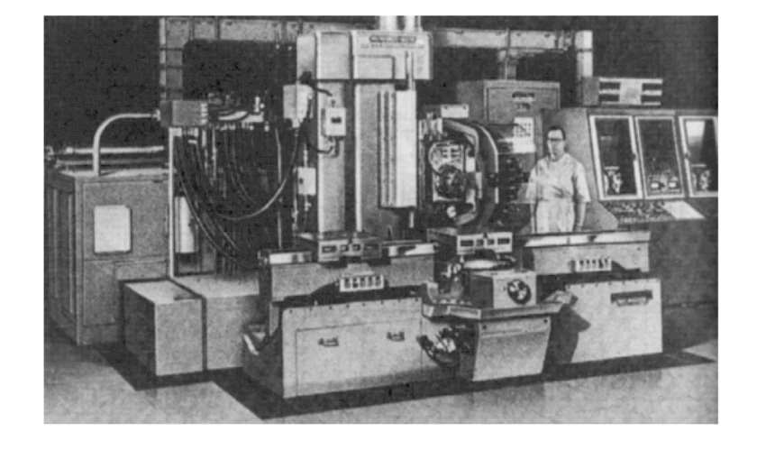
Some turning centers are equipped with dual opposing spindles, allowing one spindle to continue machining the workpiece after the other has finished, thereby enabling dual-axis control of long workpieces. Figure 1-1 shows an early turning center, which was produced in 1974.
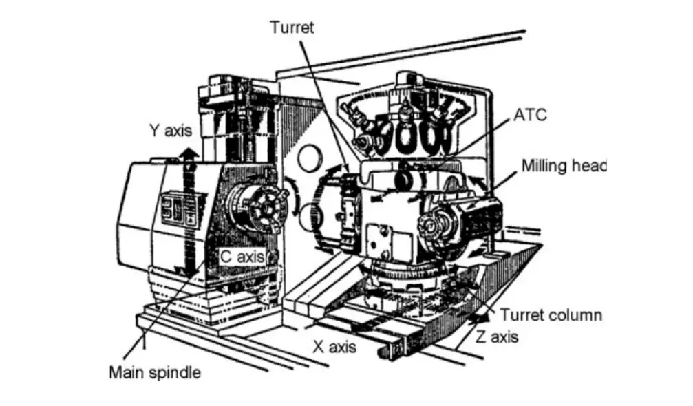
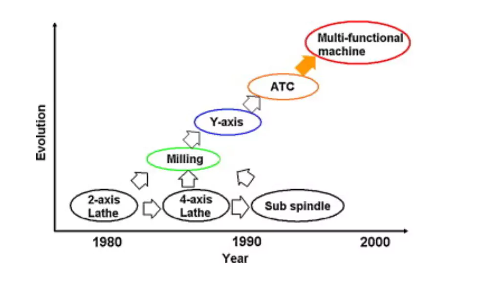
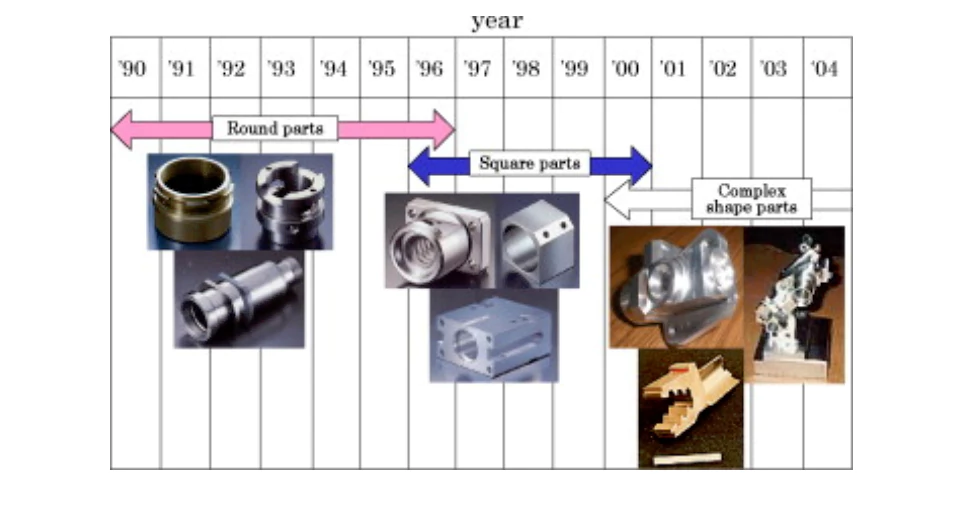
As the geometric complexity of machined parts increases, the functions of turning centers and the number of synchronous axes are also increasing. Figure 1-2 shows the development process of turning center structure, Figure 1-3 shows the axis configuration diagram of recent compound machine tools [1], and Figure 1-4 shows the development of machined parts in turning centers. Some recently developed turning centers with heavy milling heads are called combined multi-axis machine tools because it is difficult to say whether they are lathes or milling machines.
1.2 Multifunctional milling machine
The milling machine uses a multi-edged rotating tool, which was manufactured by Elly Whitney in the United States in 1827 [2]. Milling machines were initially mainly used for the processing of flat surfaces, and later expanded to the processing of 2D and 3D curved surfaces.
The first CNC machine tool was a three-axis milling machine built by John TParsons in 1952. One of the most significant advancements in CNC milling machines is the development of machining centers. The first machining center, the Milwaukee-Matic, was manufactured by Kearney and Trecker in 1958, as shown in Figure 1-5.
One of the most significant features of the machining center is automatic tool change, or automatic control of the machine tool, so it can complete multiple processing processes such as milling or drilling with one clamping of the workpiece.
Since the machining center is equipped with a rotary table and an indexing table, it is possible for the machining center to process five faces of a cube. This accessory can change the direction of the spindle from horizontal to vertical, or from vertical to horizontal, and the introduction of this function can process parts on five sides. The machining center of this period can simultaneously control the Cartesian coordinates composed of Y, Y and Z axes.
As the complexity and diversification of the shapes of processed parts increases, such as the processing of some aerospace parts, and due to the development of CNC technology and drive units, the number of synchronous axes also needs to increase. Most of the machining centers with axis control functions currently on the market are 5-axis machining centers.
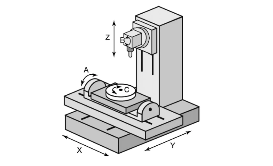
As shown in Figure 1-6, typical additional axis controls include the C axis of rotation, the A axis of the table to reverse the rotation axis, and the B axis to control the tilt of the spindle. Using a 5-axis machining center to process complex-shaped workpieces can not only improve processing accuracy but also shorten processing time.
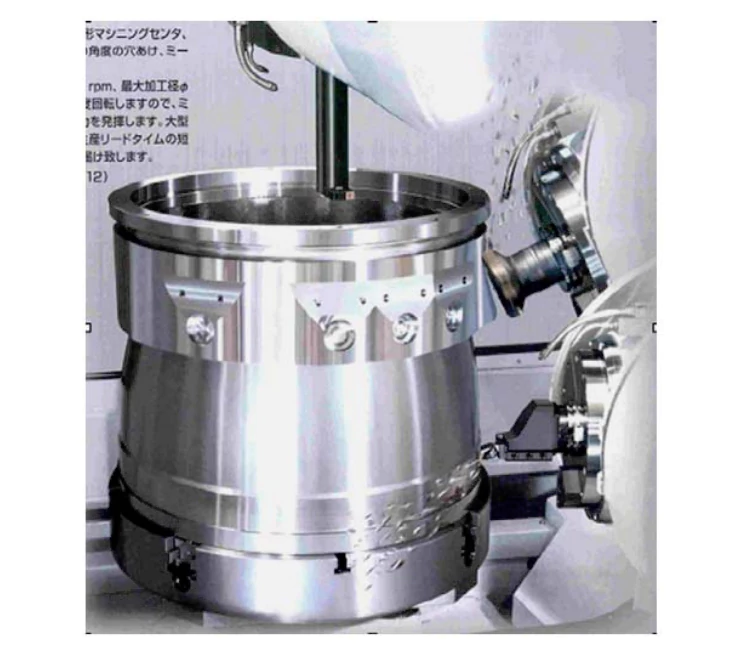
Some machining centers equipped with heavy-duty, high-speed rotary tables can be used to machine rotating workpieces, just like vertical lathes, and can also perform milling operations. Such a machining center is a machining center that integrates milling and turning. As shown in Figure 1-7, it is an example of simultaneous machining.
1.3 Design principle of compound machine tool
The cutting of the surface geometry of the workpiece is determined by the relative motion between the tool and the workpiece and the given geometry. The current basic research has analyzed the configuration and structure of the machine tool [3-5] .
One of the methods to study the structure of the machine tool is based on diversified design [6,7], and the use of existing knowledge accumulation [8-11]. The development of some analysis methods further determines the structure of the machine tool based on the geometric relationship between the mechanical elements and the tool, workpiece, and mechanical elements.
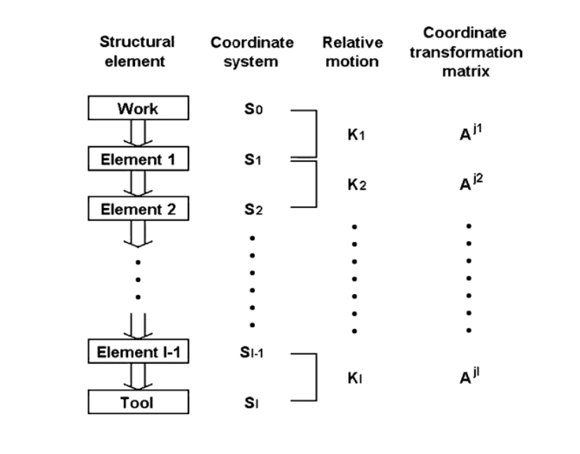
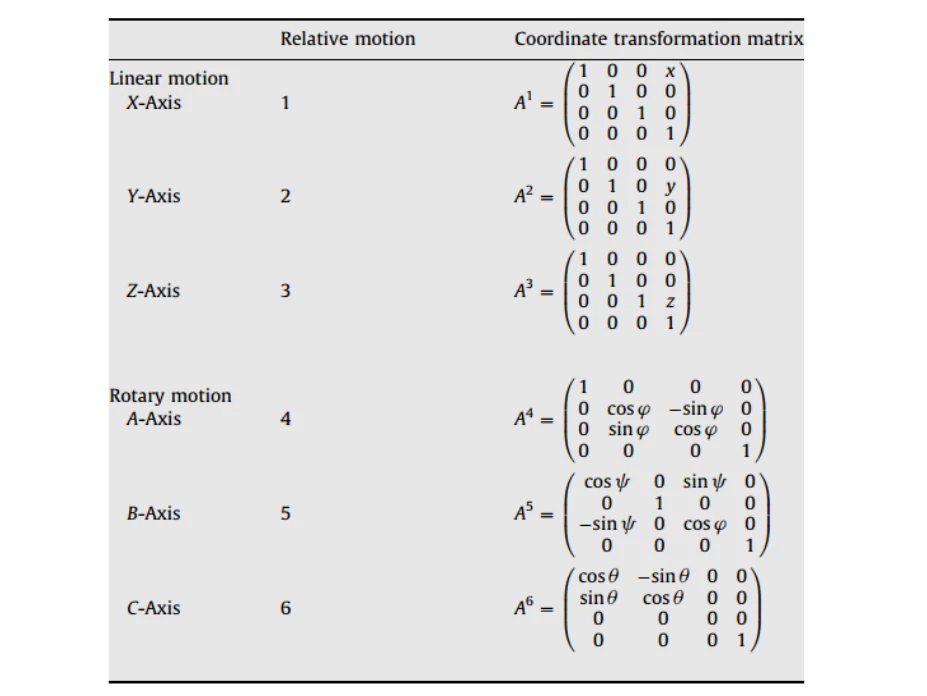
Inasaki et al. defined the mathematical model of the machine tool as shown in Figure 1-8, and the coordinate transformation model as shown in Table 1-1, where x, y, z represent parallel movement along the X, Y, and Z axes, and φ, 0 and ω represent rotational movement around the A, B, and C axes.
The generation of this motion model is mainly to describe some related motion chain structures. Imasaki also defined some machining error functions based on this method. Reshentov and Protman [12] and Moriwaki et al. used the same method to analyze and estimate the machining error of this motion model.
This analysis method can help us understand the generation process of this model and estimate the possible machining error. However, this method does not provide a better configuration of the machine tool structure for special purposes.
Some possible machine tool structure configurations are also composed of single axis linkage. To simplify the discussion, the five-axis machining center in the report is composed of three linear axes X, Y, and Z and two rotary axes. In this case, there may be 2160 possible combinations of machine tool configurations.
Excluding some configurations that are technically infeasible, such as the case of attaching the linear motion axis to the rotary axis, Sato [13] selected 216 possible vertical five-axis machining center configurations from the 2160 possible configurations mentioned above.
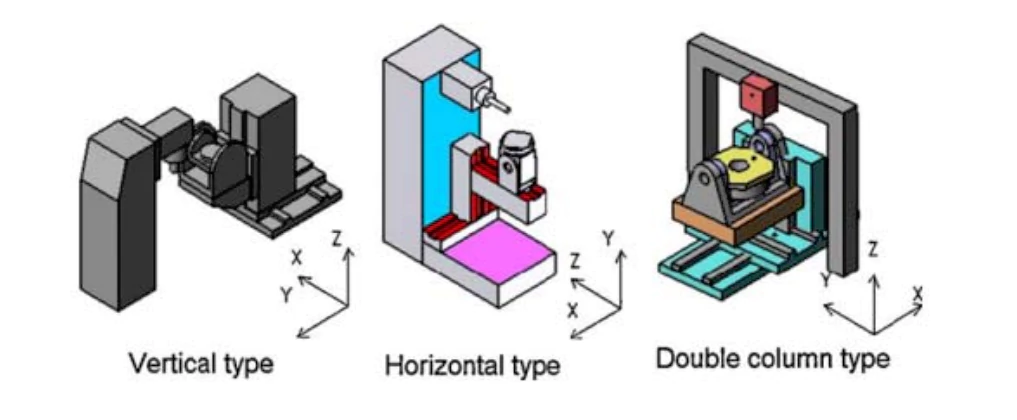
In actual machine tool design, each configuration has at least three types of structures: vertical, horizontal, and gantry. Figure 1-9 shows 216 possible combinations of vertical machining centers. Some of the possible configurations.
In fact, the structure of the machine tool is determined by the accuracy, rigidity, thermal deformation performance and ease of manufacturing that it can achieve [14,15].
The expansion function of lathes based on multi-function machine tools is relatively simple. As mentioned above, the increase in the number of rotary tables can further perform multiple tool processing.
The number of spindles is also increased from one to two, so that when the workpiece moves from one spindle to another, both sides of the workpiece can be processed. The addition of a rotary table to the milling axis and the additional linear and rotary motion further increase the multi-tasking function.
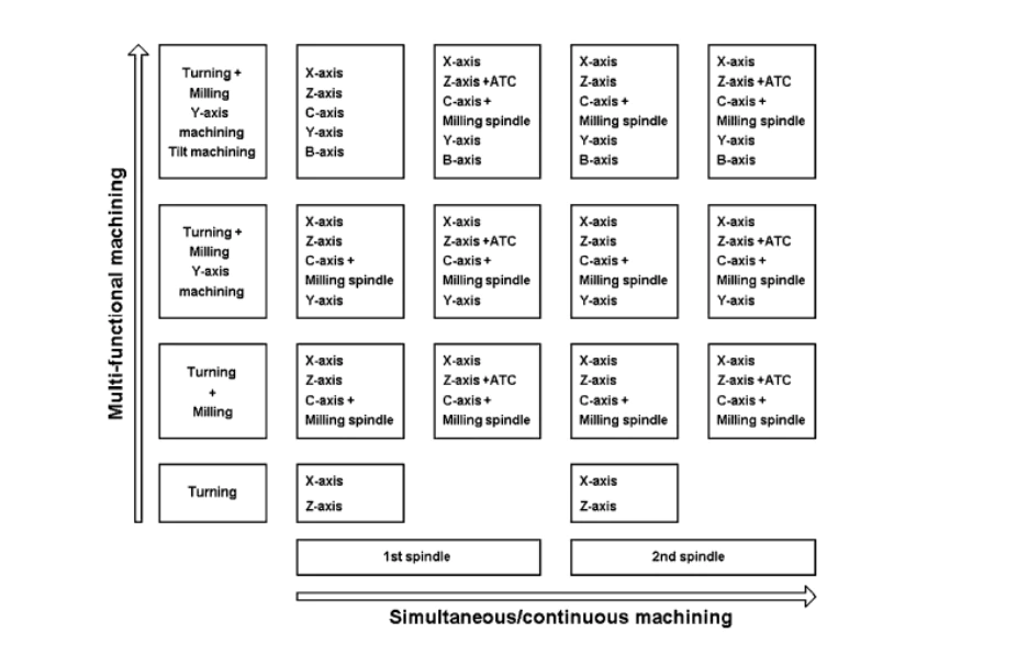
As shown in 1-10, this is the combination of the spindle and the additional rotary table [16]. Some machine tools are also equipped with automatic tool changers (ATC), and some are equipped with control axes for special purposes.
1.4 Application of multi-function machine tools
1.4.1 Application of multi-function lathes
Multi-function machine tools have been widely used in the processing of complex geometric parts, including some free-form surface processing in the aviation field, the automotive and other mechanical industries, and the machining of some mold parts. Lathes based on multi-function machine tools are mainly used for the efficient processing of some complex mechanical parts.
As shown in Figure 1-11, an efficient and highly flexible CNC turning machining center is combined with a complete CAPP/CAM system and an integrated expert system with typical machining strategies [17].
For some limitations of machine tools and technology, in order to minimize production time, the rules of the expert system are used to distribute tools/operations to different turntables, specify machining conditions, specify cutting strategies and calculate cycle time.
As shown in Figure 1-12, a recently developed lathe based on a multi-axis machine tool is equipped with two spindles and two tool holders. One tool holder is equipped with a heavy milling spindle that controls the X, Y, Z and B axes, the center of gravity or DCG, which is essentially the application of a driven tool holder. Typical feasible machining operations are illustrated in Figure 1-13.
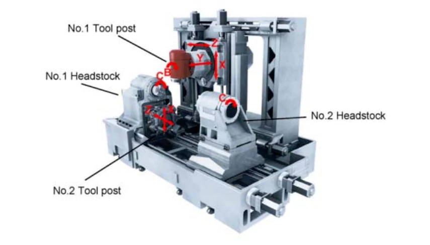
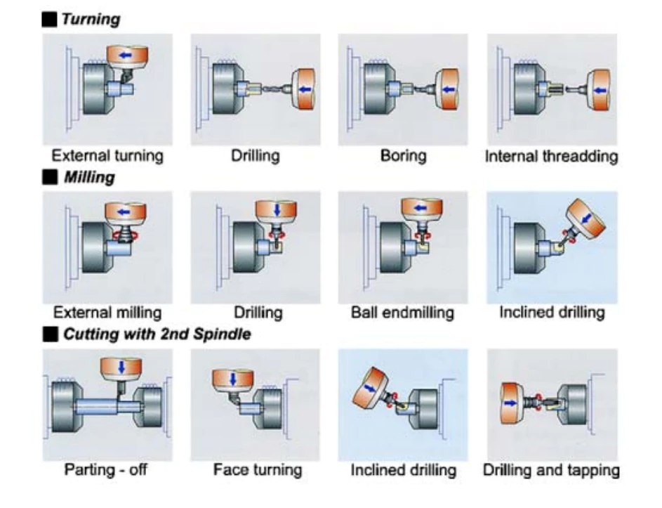
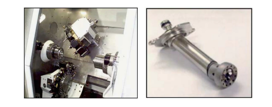
Figure 1-14 shows a high-quality, low-cost special 9-axis milling/lathe machine for gas turbine fuel nozzles. The machine is equipped with dual axes, dual rotary tables, 28 tools and a probe, and a milling head with 6 tool changers. Reducing production cycle time, reducing component assembly steps, improving performance quality, etc. are convenient and effective cost savings.
1.4.2 Multifunctional milling machine
Five-axis machining centers are widely used in the processing of some mechanical molds [18-21]. However, due to the complexity of programming, in some cases, it is not necessary to use five-axis linkage control, but 3-axis linkage control can be used to remove the additional offline 2-axis control. The spindle posture facing the workpiece is adjusted by rotational movement, and the cutting of the workpiece is controlled by traditional 3 axes. This cutting method is called 3+2 axis control machining.
One of the main advantages of this method is that programming is simple [13].
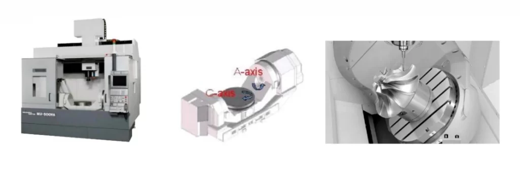
Currently, the popular five-axis machining center on the market has a tilting rotary table or trunnion table, which has two rotary axis control and three linear axis control. A typical example of a five-axis machining center is shown in Figure 1-15. Some complex shape components such as free-form surfaces are processed by this type of 5-axis machining center.
1.5 Current status of development of multi-axis turning and milling composite machining system
As a new technology that adapts to the development needs of modern manufacturing industry with multiple varieties, small batches and personalization, composite machining technology is increasingly valued by the machine tool industry. Composite machine tools have become an important development direction of CNC machine tools today.
Composite machining refers to the automatic multi-process machining of the same type of process method (such as turning, milling, drilling, keying, etc.) or multi-process machining of different types of process methods (such as cutting and laser machining) under flexible and automated CNC machining conditions. All or most of the machining processes of the workpiece can be completed sequentially on one machine tool).
Due to the advantages of concentrated process, short part processing cycle, small positioning error and high processing accuracy, composite machining can complete most or all of the machining processes on one machine tool, which can reduce the loading and unloading and handling time of the workpiece, improve production efficiency, and ensure and improve machining accuracy.
As machine tool types become more diverse and user-customized design and manufacturing models become the mainstream manufacturing model, the market demand for composite processing equipment that meets the needs of efficient processing of specific parts is increasing. At the same time, multi-channel and multi-axis control for composite processing has become an important technical feature of high-end controllers.
Take the MILLTURN series of milling and turning composite machining centers of WFL Milling Technology, a world-leading Austrian machine tool manufacturer, as an example. This machine tool has five-axis milling, turning, boring, drilling, sawing and automatic feeding functions. It uses the Siemens 840Dsl CNC system. Based on multi-axis and multi-channel control, it has tool monitoring, real-time collision protection, online measurement and various error compensation functions.
Through the study of high-end CNC systems for milling and turning composite machining of mainstream system manufacturers, it is found that in order to maximize the advantages of composite machining centers, high-end CNC systems for milling and turning composite machining must have the following characteristics [22].
- High speed, high efficiency, and high reliability
Machine tools are developing towards high speed and high efficiency. While giving full play to the performance of advanced tool materials, they can greatly improve processing efficiency, reduce enterprise costs, and achieve higher and better processing quality and precision. Ultra-high-speed processing control technology has wide applicability for the manufacturing industry to achieve high-efficiency, high-quality, and low-cost production.
At present, new breakthroughs have emerged in ultra-high-speed high-torque spindle units, high-speed and high-response feed motion components, and high-performance service systems, reaching new technical levels. These technological breakthroughs have put forward higher requirements for high-speed and high-precision control of high-end CNC systems.
In order to improve the processing speed and precision of CNC machine tools, the program segment processing function of the CNC system has been continuously improved.
SIEMENS 840D defines high-speed processing cycles, which can determine the corresponding control parameters according to the processing technology, and introduces the intelligent path control function (Intelligent Path Control) to expand the forward range of the program segment to the adjacent processing paths to improve the surface processing quality of the workpiece. In the implementation of the system, 80-bit NANOFP technology with 80-bit floating-point calculation accuracy is adopted to make the system control accuracy exceed microns and nanometers.
- Multi-axis multi-channel control
The emergence of multi-axis milling and turning machining centers has made it possible to use one CNC device to achieve the machining capabilities of multiple CNC devices, and has put forward clear requirements for the multi-axis multi-channel control of CNC systems.
The CNC system channel is the machining control process of the CNC system. Its control object is a complete motion closed-loop system composed of feed axis, PLC axis, tool magazine axis, spindle, etc., which can be independently controlled by its corresponding machining program. Based on the concurrent processing capability of the CNC system hardware processor, each channel can run independently and concurrently, or work in collaboration with each other.
Each channel has the same machining process, that is, it is a CNC machine tool with multi-channel multi-axis linkage function, such as a dual-process crankshaft milling machine. If each channel has a different machining process, it is a compound machining machine tool, such as a milling and turning machine tool.
In order to realize the machining control function of the above machine tools, the CNC system should have the coordinated control between channels and multi-channel multi-axis linkage function [23].
- Five-axis linkage processing capability
Five-axis processing function means that in high-end CNC systems with five-axis linkage control capability, the controller can provide a simple and efficient programming method for five-axis machine tools or tools with various configuration structures, integrate complex five-axis processing tasks from conventional complex multi-processes into a single simple operation, and effectively guide users to operate during the entire processing process. At the same time, it can also optimize motion control in special processing tasks.
Currently, high-end systems of major CNC system manufacturers, such as ANUC’s 30i, Siemens’ 840Dsl and Heidenhain iTNC620, all use five-axis processing function as one of the iconic functions of their high-end products [24-26].
The five-axis processing functions of the FANUC system mainly include: RTCP function, tool posture control, tool front/side compensation, inclined surface processing and inclined rotation axis control.
The five-axis machining functions of the Siemens system mainly include: five-axis kinematic conversion function, 3D face milling tool radius compensation, 3D circular milling tool radius compensation, large arc interpolation, frame programming function, etc. The five-axis machining functions of the Heidenhain system mainly include: RTCPM, three-dimensional tool compensation, PLANE function of tilting machining, etc.
- Composite machining capabilities
Complexification includes process compounding and function compounding. The development of CNC machine tools has gradually blurred the concepts of rough and fine machining processes. In order to improve productivity, the development and manufacture of CNC turning and milling compound machining machines has become a development trend of CNC machine tools.
Composite machining is an important function of high-end CNC devices and an effective means to realize complex parts machining. Through the combination of various processes and processes, it is possible to complete all the machining of multiple processes on the same machine tool and in one clamping, thereby shortening the machining cycle and improving the machining accuracy of the workpiece.
In addition to the commonly used turning, boring and milling machining, it can also realize deep hole drilling, inner diameter machining, gear hobbing, inner diameter spline forming, high-precision machining, etc. At the same time, with the help of the B-axis, the machine tool can complete processing from any angle to the center line. Arranging these processes on the same CNC machine tool can greatly improve productivity.
Therefore, for compound CNC machine tools, it is necessary to first add many software function packages for special operation processing. For example: turning processing of rotating B axis, turning and milling processing, crank pin milling processing, cam milling processing and deep hole drilling processing. These software function packages make complex operation processing easy [27-30].
For example, SINUMERIK 840D has not only turning and milling processing functions, but also thread tapping and grinding processing functions. In addition, the tool compensation function also needs to have both turning and milling functions.
Turning and milling combined processing has developed rapidly around the world in recent years due to its own advantages. As early as September 1996, the German SPINNER company launched the TM-CNC seven-axis turning and milling compound machining center at the AMB exhibition. The machining center adopts the SIEMENS 840D CNC system and a dual-spindle design. Its work efficiency is equivalent to that of two five-axis machining machines. The combination of centers [28].
The S192F turn-milling composite machining center of Swiss Baume Company uses the FANUC 31i CNC system and has five-axis milling, turning, drilling and other functions [29]. The M series of the Austrian WFL company and the E-H series of the Japanese MAZAK company.
Domestic ones include the CXHA6130 turning and milling compound machining center of Beijing No. 1 Machine Tool Factory, the HTM series of turning and milling compound machining centers of Shenyang No. 1 Machine Tool Factory, and the CHD25 nine-axis five-linkage turning and milling center of Dalian Machine Tool Group [31].
So many companies have increased their investment in turning and milling composite processing, hoping that this technology can bring greater benefits to the company.
In 1955, H. Weber of Germany made a detailed analysis of parameter rotation during cylindrical milling. This article played a vital role in promoting subsequent research on turning and milling technology [32].
Two important turn-milling research centers in Germany, RWTH Aachen University and TU Darmster, have combined the research results of turn-milling composite processing technology with practice and created a new field of turn-milling composite processing technology.
The United States and some other countries are also committed to research on turn-milling composite processing technology. Literature [33,34] all study the roughness of the workpiece surface when processing parts using turn-milling composite processing technology.
There is also related research on turn-milling composite processing technology in China. For example, “Principles of Turning and Milling” written by Jia Chunde and Jiang Zenghui introduces the relevant basic concepts, principles and virtual machine tool simulation of turn-milling composite processing technology.
At present, our country’s research on turn-milling composite processing technology has covered many aspects such as basic theory, processing technology, design and manufacturing, and already has independent intellectual property rights. However, due to its late start and imperfect related technical foundation, it still has some differences from foreign countries. There is a certain gap.
1.6 Structural analysis of turning and milling compound machine tool HTM63150iy
Domestic research on five-axis turning and milling centers began in 2000, and the first five-axis turning and milling center SSCKZ63-5 was manufactured in 2001; in the same year, the key project SSCKZ80-5/2000 of the “Tenth Five-Year Plan” National Science and Technology Research Plan was launched and Shenyang Machine Tool was responsible for the research of this project. In 2003, the project passed the national acceptance and won the second prize of China Machinery Industry Scientific Progress Award in 2005.
On this basis, Shenyang No. 1 Machine Tool Factory developed the high-end turn-milling compound machine tool HTM63150iy (Figure 1-16). This machine tool was highly favored at the 2008 CCMT China CNC Machine Tool Exhibition. It is also the first domestic research and development of turn-milling compound machine tools. A masterpiece in this regard [35]. The HTM63150iy machine tool is market-oriented and integrates advanced domestic and foreign technologies. It can complete the complete processing of the workpiece by clamping it once. It is especially suitable for the current military and aerospace fields that require particularly high processing accuracy of parts. high-end field.
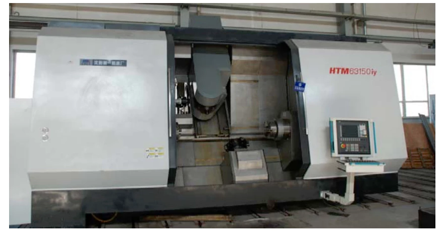
The overall layout of this type of machine tool adopts the traditional horizontal lathe layout, the bed adopts a highly rigid inclined bed structure, and the guide rails are specially designed large-size linear guides with high rigidity and excellent vibration resistance. The left end of the bed is the turning spindle box, which has C-axis function.
The right end is the second turning spindle. The upper part of the inclined bed is a turning, milling and boring spindle device, which can perform linear motion along the longitudinal (Z-axis), transverse (X-axis), radial (Y-axis) and swing and rotary motion on the B-axis.
The lower part of the inclined lathe is a center bracket that can be motorized both longitudinally and transversely. It is used to support the workpiece when the tailstock device cannot be used for end face and boring inner hole processing.
Therefore, this type of machine tool has X, Y, Z, B and C multi-axis interpolation linkage functions, and can perform turning, drilling, milling, grinding, gun drilling, internal and external gear processing, turning and milling without human intervention , arc milling and other processing tasks.
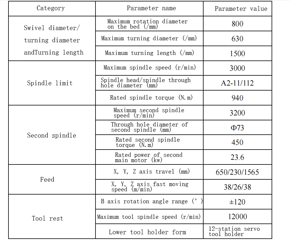
This turning and milling compound machine tool can realize multi-axis linkage to complete the actual processing of parts. In particular, the addition of the B-axis has become the core component of the machine tool, and all technical parameters of the machine tool have reached the leading domestic level. , Table 1-2 lists some main parameters.
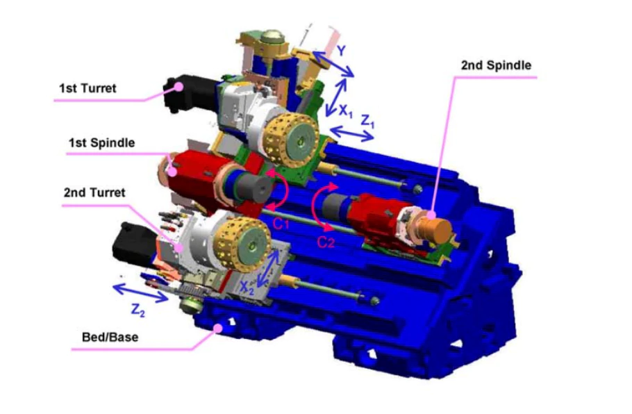
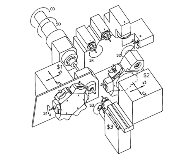
This machine tool is a turning and milling compound processing machine tool. When processing parts, it will include the two basic processing methods of turning and milling. Therefore, the number of spindles and tool magazines equipped with the machine tool will increase. The distribution of the spindle and tool magazine of the machine tool is as shown in the figure. 1-17 shown.
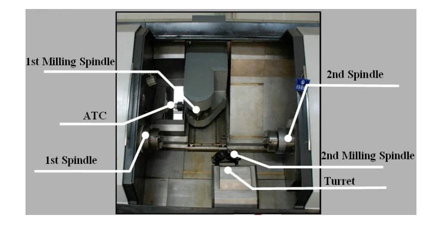
As shown in Figure 1-17, the multi-axis turning and milling compound machine tool HTM63150iy is mainly equipped with 4 spindles, including two turning spindles (1st/2nd Spindle) mainly for turning functions, a milling spindle (1st MillingSpindle), and a milling spindle. Power head (2nd Milling Spindle), 8-position turret (Turret) and automatic tool changer (ATC Auto Too1 Changer).
The multi-process turning and milling compound processing of parts by this machine tool is mainly completed through the cooperation of the movement of each axis of the machine tool. In order to facilitate the analysis of each axis of the machine tool, each motion axis of HTM63150iy is extracted for analysis (Figure 1-18).
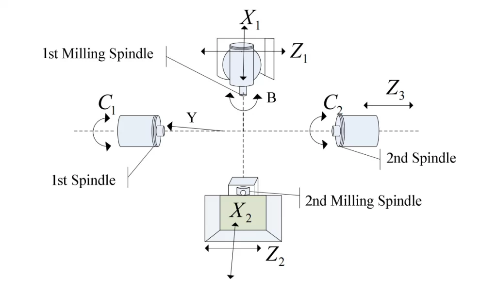
As shown in Figure 1-18, the machine tool has 3 linear Z axes (Z1, Z2, Z3), 1 tilted Y axis and 2 X axes (X1, X2), and the rotary axes are C1, C2 and B. The rotary axis C1 spindle is fixed on the machine tool, while C2 is realized based on the CS axis switching of the second spindle, and can move along the Z3 axis.
Y axis: The traditional primary turning and milling machine tool is based on the lathe and adds an additional milling spindle (power head) to realize the milling of the end face and cylindrical surface of the turned parts.
At this time, when milling the end face and cylindrical surface on the workpiece, the only way to do it is to use the machine tool spindle (C axis) and the X axis for polar coordinate interpolation, and the Z axis for cylindrical interpolation. The fatal disadvantage is that the milled plane is not a theoretical straight line but a straight line fitted by a circular arc with a large radius of curvature, and the processing efficiency is low.
In order to achieve eccentric processing, the Y axis is added on the basis of the turning center. By controlling the Y axis, the machine tool can perform eccentric processing on any end face and side to achieve multi-directional milling processing.
B axis: The machine tool is additionally equipped with a rotating axis B axis on the tilting axis. The B axis head can be used as a milling spindle and a turning/boring tool holder, so that the machine tool can complete all milling and turning operations in a single clamping. At the same time, based on the rotation of the B axis, the tool can be processed to some areas that are difficult to process due to the size of the tool.
C-axis: Multiple C-spindle operation modes. The indexing function of the C-spindle effectively increases the milling processing range; the positioning mode of the C-axis facilitates multi-faceted processing such as drilling, milling, and tapping of inclined surfaces; the interpolation mode of the C-axis cooperates with the B-axis for five-axis linkage processing.
Based on the above-mentioned axis combination, the machine tool can realize the processing of some complex curved surfaces. The dual spindles equipped with the machine tool can process both ends of the workpiece in one clamping, and the movement mode of the B-axis adopts the slide movement mode, which increases the movement speed. This combination makes the performance of the machine tool as much as possible. This type of machine tool structure can integrate the turning and milling processes and has gradually become the mainstream of the composite processing market [36,37].
References:
- [1]Nakaminami M, Tokuma T, Moriwaki M, Nakamoto K. Optimal Structure Design Methodology for Compound Multiaxis Machine Tools. I. Analysis of Requirements and Specifications[J]. International Journal of Automation Technology1(2):78–86,2007.
- [2]Woodbury RS. Studies in the History of Machine Tools[M]. MIT Press, 1972.
- [3] Ito Y, Shinno H. Structural Description of Machine Tools[J]. Transactions of JSME Series C 46(405):562–571,1980.
- [4] Riegg A, Gygax PE. A Generalized Kinematics Model for Three to Five Axis Milling Machines and their Implementation in a CNC[J]. Annals of the CIRP 41(1):547–550,1992.
- [5] Spicer P, Koren Y, Shpitalni M, Yip-Hoi D. Design Principles for Machining System Configurations[J]. Annals of the CIRP51(1):275–280,2002.
- [6] Masahiko Mori, Makoto Fujishima, Oda Yohei, 5 Axis Mill Turn and Hybrid Machining for Advanced application[J]. Procedia CIRP, Volume 1:22-27, 2012.
- [7] M. Kannan, J. Saha. A feature-based generic setup planning for configuration synthesis of reconfigurable machine tools[J]. The International Journal of Advanced Manufacturing Technology, 43(9-10):994-1009, 2009.
- [8] Reinhart G, Reinhardt S, Foeckerer T, Zaeh MF. Comparison of the resource efficiency of alternative process chains for surface hardening[J]. Proceedings of the 18th CIRP international conference on life cycle engineering, Braunschweig, Germany, pp 311–316, 2011.
- [9] Kolkwitz B, Foeckerer T, Heinzel C, Zaeh MF. Experimental and numerical analysis of the surface integrity resulting from outer-diameter grind-hardening[J]. Procedia Eng 19:222–227, 2011.
- [10] Shinno H, Hashizume H. Structured Method for Identifying Success Factors in New Product Development of Machine Tools[J]. Annals of the CIRP 51(1):281–284, 2002.
- [11] Shinno H, Hoshioka H, Marpaung S. A Structured Method for Analyzing Product Specification in Product Planning for Machine Tools[J]. Journal of Engineering Design17(4):347–356, 2006.
- [12] Reshetov DN, Protman V, Accuracy of Machine Tools[M]. ASME Press,1981.
- [13]Sato M. Design and Performance of 5-axis Machines in Japan[J]. Proceedings of the 12th International Conference on Machine Tool Engineer’s, 167–189, 2006.
- [14] Karagüzel, Umut, et al. High Performance Turning of High Temperature Alloys on Multi-Tasking Machine Tools[J]. New Production Technologies in Aerospace Industry. Springer International Publishing, 2014. 1-9.
- [15] Nakaminami M, Tokuma T, Matsumoto K, Sakashita S, Moriwaki T, Nakamoto K. Optimal Structure Design Methodology for Compound Multiaxis Machine Tools. II. Investigation of Basic Structure[J]. International Journal of Automation Technology,1(2):87–93, 2007.
- [16] Nagae A. Development Trend of Multi-tasking Machines[J]. Proceedings of the 11th International Conference on Machine Tool Engineers, 312–323, 2004.
- [17] Mayr, J., Jedrzejewski, J., Uhlmann, E., et al. Thermal issues in machine tools[J]. CIRP Ann.Manufact. Technol.61(2), 771–791, 2012.
- [18] Abele, E., Altintas, Y., Brecher, C. Machine tool spindle units[J]. CIRP Ann. Manufact.Technol.59(2), 781–802, 2010.
- [19] Altan T, Lilly B, Yen YC. Manufacturing of Dies and Molds[J]. Annals of the CIRP50(2):405–423, 2001.
- [20] Jedrzejewski, J., Kowal, Z., Kwasny, W., Modrzycki, W.: Hybrid model of high speed machining centre headstock. CIRP Ann. Manufact. Technol.53(1), 285–288, 2004.
- [21] Jedrzejewski, J. Thermal problems in machine tools design and operation[J].Introduction to precision machine design and error assessment, pp. 75–127. CRC Press, 2009.
- [22] Chi Liting. Development status and trends of CNC technology [J]. Shanxi Science and Technology. 2009(4):81-82.
- [23] Li Lin, Chen Songxin. Current status and development trends of CNC technology research [J]. Science and Technology Entrepreneurship Monthly. 2010(9): 85-86.
- [24] Su Hao. Research and development of five-axis linkage dual-channel turning and milling composite CNC decoding system [D]. Shanghai. Shanghai Jiao Tong University. 2009.2.
- [25] Xu Wei. Research on functional planning and key technologies of high-end CNC systems [D]. Shanghai. Shanghai Jiao Tong University. 2009.5.
- [26] Lu Qijian, Chu Huisheng. High-speed cutting and five-axis linkage machining technology [M]. Beijing. Machinery Industry Press. 2010.11.
- [27] Chen Guowen. Prospects for the application of turning-milling composite processing technology in the aviation industry [J]. Aviation Precision Manufacturing Technology. 2010(02):26-27.
- [28] Liang Wei. Dynamic study of axial turning and milling of typical workpieces[D]. Shenyang. Shenyang Ligong University. 2009.3.
- [29]Chen Xiaohua, Liu Zhibing, Wang Xibin. Analysis of kinematic characteristics of typical parts turning and milling combined processing [J]. Computer Integrated Manufacturing Systems. 2013(7):1569-1576.
- [30] Wu Baohai, Yan Yanan, Luo Ming, Zhang Dinghua. Key technologies and application prospects of turning and milling composite processing [J]. Aviation Manufacturing Technology. 2010(19):42-45.
- [31] Yang Lin. Research on CNC turning and milling composite machining program simulation system [D]. Chongqing. Chongqing University. 2010.5.
- [32] Zhu Lida. Simulation and experimental research on dynamic characteristics and processing mechanism of turning and milling machining centers [D]. Shenyang. Northeastern University. 2009.5.
- [33] S K Chouldhury, J B Bajpai. Investigation in orthogonal turn-milling towards better surface finish [J]. Materisls Processing Technology. 2005.170(45):487-493.
- [34] Kwasny, W., Turek, P., Jedrzejewski, J.: Survey of machine tool error measuring methods[J]. J. Mach. Eng.11(4), 7–38, 2011.
- [35] Liu Yan, Jin Minggang, Li Hongyu, Xiao Kai. The first turn-milling compound machining center using domestic five-axis CNC system [J]. Equipment Management and Maintenance. 2009(01):53-54.
- [36]T.Moriwaki.Multi-function machine tool [J]. Annals Manufacturing Technology. 2008:736-749.
- [37]David Yang. Research on tangential turning and milling motion modeling and theoretical surface roughness [D]. Shenyang. Shenyang Ligong University. 2010.3.