
A machine tool fixture is a device for mounting a workpiece on a machine tool. Fixtures ensure the correct position of the workpiece relative to the machine and tool, maintaining this position during processing. They are vital for product quality, efficiency, worker safety, and reducing labor intensity. However, with the continuous development of modern processing technology, the challenges faced by fixture research and development are also increasing.
The time spent on fixture design and inspection is a major portion of the production cycle, making it crucial to shorten these times and improve design reliability. Rapid Prototyping (RP) is an advanced manufacturing technology developed in the late 1990s. It directly accepts 3D product data, bypassing traditional tools like cutting tools and fixtures, and quickly converts virtual models into functional solid models for manufacturing complex-shaped products. This allows designers to intuitively experience the design, verify its rationality, assemblability, and aesthetics, and promptly identify and improve design issues.
In this paper, we use rapid prototyping technology in the research and development of fixtures. Rapid prototyping technology enables the materialization of product CAD data at any R&D stage, aiding in fixture design, inspection, and optimization, thus shortening development cycles and reducing costs.
Defects in fixture design at this stage
With the rapid advancement of microelectronics, computer, and automation technologies, the manufacturing industry is moving towards higher speed, precision, flexibility, and intelligence. The use of parallel engineering and CNC processing has greatly improved product quality and shortened development cycles. However, due to the improvement in processing accuracy, speed, ed, and process concentration, the requirements for fixtures are higher.
1. Defects of concurrent engineering fixture design
Concurrent engineering is an integrated, systematic approach to designing products and their related processes, considering all factors in the product design cycle and aiming for success on the first attempt while designing sub-processes. Sub-processes usually include process design, tooling design, etc.
Fixture design is an important sub-process in the concurrent design process of products. The computer-aided fixture design (CAFD) and CE-CAFD system based on PDM, proposed by Chen Weifang et al., play a key role in sub-process design. However, concurrent engineering only overlaps sequential work in time and space, with subsequent processes still relying on upstream theoretical data. For instance, designers often limit fixture design to drawings or graphics, even in concurrent engineering, without referring to a prototype.
2. Defects in fixture design for CNC machining
CNC machining, a key component of modern manufacturing, is a versatile machine tool that integrates milling, drilling, reaming, tapping, and boring. It can automatically change tools and perform one-time processing on the workpiece. CNC machine tools that can process multiple processes after clamping. The concentration of processes and automatic tool changing reduces auxiliary operations like clamping, measurement, and adjustment, cutting machine tool processing time to about 80% of startup time (compared to 15-20% for ordinary machines). This also shortens product production cycles, improving economic efficiency.
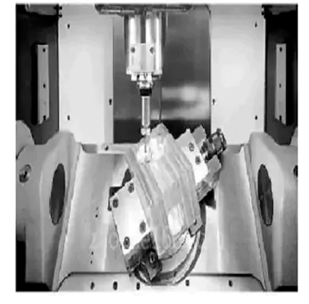
The complex motion trajectory of CNC multi-axis machining, shown in Figures 1 and 2, makes fixture requirements more stringent. The fixture must accommodate CNC multi-faceted machining and avoid interference with the tool’s motion trajectory, including from fixture components ts. The fixture structure must not hinder the tool’s multi-sided processing of various parts of the workpiece.e

To solve these problems, we currently mainly use the observation method, assembly simulation, and processing simulation methods. The so-called observation method relies on the designer’s experience to make judgments. Assembly simulation and processing simulation use some software’s assembly, motion modules, and processing modules to simulate. To judge the rationality of the fixture design. We must continuously revise a suitable fixture to meet actual processing needs. The above method is carried out in a virtual environment and inspected in an ideal state. It cannot fully consider various situations during processing. Actual clamping and processing inspection requires waiting for the test piece prototype. You wasted a lot of time.

Application of rapid prototyping technology in fixture design
The fundamental issue with concurrent engineering and fixture design for CNC machine tools is the lack of test piece prototypes. Rapid prototyping technology can quickly convert product data into physical test pieces for fixture design, clamping inspection, and processing validation, addressing these shortcomings.
Rapid prototyping helps develop fixtures for parts, as shown in Figure 3. In concurrent engineering, designing fixtures based solely on computer drawings or graphics avoids the issues of lacking physical models. This enables smooth information exchange between design stages, allowing quick creation of physical models and reducing rework, improving the likelihood of successful design, and maximizing the benefits of concurrent engineering.

For CNC machining with complex motion, rapid prototyping technology develops fixtures and processes solid models. In addition to aiding fixture design, clamps, g, and processing inspections are crucial. CNC machine tools process complex parts, and their fixtures are often intricate, leading to potential interference between fixture components oh cutting tools. A solid model allows for actual clamping and processing inspections, rather than relying solely on virtual software simulations. To ensure the feasibility and rationality of the developed fixture, we combine theory and practice.
Rapid prototyping of models
As shown in Figures 4 and 5, these are the three-view and modeling drawings of a semi-finished part. Traditionally, fixture design relies on the designer’s experience and three-view or modeling drawings, which has many limitations. Using rapid prototyping to produce samples, as shown in Figure 6, can provide designers with intuitive references.


The rapid prototyping machine is the MEM320A melt extrusion model, using ABS B601 as the molding material and ABS S301 as the support material. The rapid prototyping machine processes the steps shown in Table 1.

Traditional design methods require several weeks to verify fixture design and produce prototypes, involving processes like casting, heat treatment, drilling, and rough milling. In contrast, rapid prototyping technology takes only about 90 minutes, reducing waiting time, speeding up development and inspection, enabling parallel engineering, and minimizing losses from CNC machining interference.

Conclusion
Industries such as electrical appliances, transportation, aerospace, industrial design, and healthcare widely use rapid prototyping technology for its speed, flexibility, and high integration. Researchers in the fields of art and architecture have also begun to use RP equipment. RP technology plays a key role in the product design stage, where it is used for evaluation, review, structural inspection, and mold design. When used in fixture design, some CAD surface information may be lost during the conversion of the 3D model to STL format, but this does not affect its functionality in fixture design. RP technology has created a shortcut in the research and development of fixtures. This design and inspection based on solid models is more reliable and more convincing.

