Table of Contents
With the development of the automotive industry, reverse engineering has become an essential means of product innovation and rapid prototyping.
Reconstructing a product’s CAD model through Reverse Engineering software can provide an effective model for part redesign and lightweight design and prepare for rapid prototyping and CNC machining.
However, complex, porous parts such as end caps still face challenges in rapid prototyping.
Engineers fit curved surfaces and stitch them together using traditional methods. However, mistakes in the stitching sequence or trimming process can cause the model to fail.
This study analyzes errors in reverse modeling using the end cap of an imported generator as an example. Researchers identify the errors and correct them with the secondary forward design method, which improves modeling accuracy.
Researchers verify the method’s feasibility by performing 3D printing. They also propose a solution to control both printing accuracy and surface quality.
Here, we need to prove that we oppose using technology to gain illegal benefits.
In practice, we need to respect intellectual property rights and the efforts of our peers to avoid legal disputes.
In this article, we use the methodology only to verify its technical realizability.
Point cloud data acquisition and pre-processing
1. Point Cloud Data Acquisition
In this example, researchers use a COMET L3D 3D structured light scanner to acquire the 3D point cloud data of the generator end cover.
They control the scanner’s error within 0.03 mm. Figure 1 shows the physical model of the generator end cap.
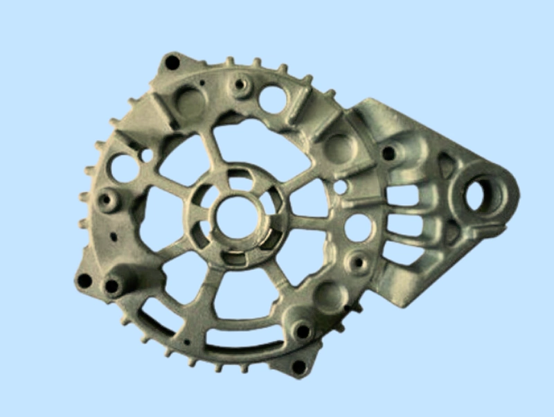
Fig. 1 Physical model of the generator end cap
Researchers scan the inner and outer surfaces of the end cover twice. They splice and encapsulate the obtained point cloud data to generate the complete point cloud data of the generator end cover.
2. Point cloud data repair
Usually, the scanned point cloud data contains abnormal data, such as bad points, jumping points, etc.
Geomagic Studio software provides a powerful repair function to repair the initial point cloud model.
These areas represent geometric features that the scanner did not capture.
This issue may occur because some features on the part are too deep. Shading can block the scanner’s light. This blockage may prevent full exposure in some areas.
In addition, the edges of the finishing surfaces of the part are susceptible to blunting.
To ensure smooth model reconstruction, repair the yellow areas. Use the “Hole Fill” command in the software for this purpose.
According to the modeling experience, the surface of the repaired deep hole structure should have atlea213-point cloud data.
This way, you can use the three-point circle command. It will accurately fit the center of the deep hole feature during model reconstruction.
3. Coordinate System Construction
Constructing the model’s coordinate system correctly is crucial throughout the preprocessing process. This will affect the accuracy of the subsequent CAD model building and reconstruction.
In Geomagic Studio, when building the coordinate system, you can select the inner surface of the model point cloud data to fit the rotary axis of the end cap.
First, use the lower surface of the end cap opening to fit the optimal plane as the X datum plane.
Since the generator end cap is a rotary body part, it only needs a plane. The axis is perpendicular to that plane. These will complete the constraints during the coordinate system establishment.
This way, you can determine the XY plane and Z axis of the generator end cap under the global coordinate system. This allows for properly creating the coordinate system for the point cloud data.
The process of creating the coordinate system is shown in Fig. 2.
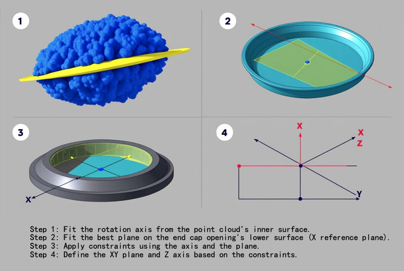
Fig. 2 Creating the coordinate system
CAD Model Construction
After you complete the pre-processing of point cloud data, you can start the model reconstruction.
By analyzing Fig. 2, you can see that the non-contact scanner’s working characteristics cause breakage and edge blunting in the point cloud data.
The defects in the initial point cloud data from scanning prevent its direct use for rapid prototyping.
Therefore, you need to perform a secondary reconstruction of the point cloud data to achieve rapid prototyping of the model.
CAD systems widely use cubic B-spline curves and NURBS spline curves for curve and surface fitting. These curves offer good smoothness and controllability.
To complete the model reconstruction efficiently and accurately, import the 3D digital model of the generator end cover into CATIA in STL format. Then, create a 3D solid model.
1. Hybrid modeling method in reverse engineering
In reverse engineering, the reconstruction of the CAD model mainly adopts the hybrid modeling idea of “forward/reverse combination.” The essence of the design lies in the following points:
(1) Utilize the camber or rotation commands in the part design module to draw the general shape of the part.
(2) Use the pre-processed point cloud data as the datum for part design.
(3) Obtain the shape information of the point cloud model cross-section in the reverse point cloud editing module as a datum for the solid feature sketch of the part.
(4) Complete the reconstruction of solid features and surfaces by using the commands of stretching, rotating, and sweeping in the Created Shape Design Module and the Inverse Surface Reconstruction Module, together with the commands of camber, not,h, and fillet.
(5) In the reconstruction process, to ensure the accuracy of the inverse direction, the underlying sketch or the fitted surface must be adjusted each time the solid features are reconstructed.
This repeated adjustment can significantly improve the fitting accuracy.
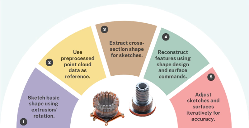
Fig. 3 Five Steps of 3D Modeling
2. Detailed Processing in Model Reconstruction
2.1 Error and Correction
The reconstructed model is a casting, which is already a molded product. Due to the mold manufacturing, casting, machining,g, and assembly process, there will be errors and damage.
Coupled with the inevitable errors of scanning equipment, there will be a certain gap between the point cloud data and the design dimensions.
Therefore, designers must redesign part of the underlying sketch during reconstruction. This helps restore the model’s original design structure as much as possible.
You can see this by observing the structure of the end cap:
(1) The end cap is a rotating body part with various irregular heat dissipation holes and hanging corners in its external distribution.
In the inverse point cloud editing module, the system intercepts the largest cross-section of the end cap. This section serves as the sketching reference for the solid rotational features.
(3) Import the cross-section into the part design module, sketch it concerning its shape, and perform the rotation operation to obtain the solid shape of the end cap.
2.2 Fitting of hole features
The truncation method obtains the shape of the heat sinkhole cross-section.
The system combines spline curves with three-point arc commands to fit irregular holes.
The process creates the hole features through solid excision. The Creation Shape Design module fits a flat surface in F or non-through-hole structures.
Then, the system creates the feature using the “Hole Stretch to Face” command. For deep hole features, the three-point circle command fits the center of the hole. For difficult-to-measure hole structures, you can use a silicone mold flip to obtain the structural feature.
2.3 Solving the Edge Blunting Problem
Linearly approximating the blunted position can solve the problem of edge blunting in the model’s point cloud data.
3. Reconstruction results and accuracy testing
After completing the reconstruction, the system generates the CAD model. It extracts the surfaces of the CAD model using the surface extraction command. Then, it compares the surfaces with the pre-processed point cloud data model.”
The accuracy detection results show:
The maximum positive error is 0.993 mm, and the maximum negative error is -0.996 mm.
The generator end cover is a casting model. The system controls its error at ±0.5 mm. This error fully meets the manufacturing requirements.
Rapid prototyping of end caps
1. Use of industrial-grade 3D printers to produce generator end caps
During the trial manufacturing process of the end cover prototype, the FDM360mc industrial-grade 3D printer completes the production of the generator end cover.
The most commonly used data format for 3D printing is the STL format. People most commonly use the STL format in 3D printing. So, we use the STL file format to complete the layering and slicing of the model.
1.1 Ensure the model store
Before layering, it is important to ensure the reconstructed end cap CAD model is free of solid intersections and cracks. The generated STL file should also be free of holes.
After data processing, the resulting STL file may contain “errors”. These errors do not show up in normal modeling software but can cause interruptions during the 3D printing process, which can cause the entire printing process to fail.
1.2 Model checking with Netfabb software
Open the model file in the Netfabb software to verify it and avoid problems. The STL file has no loopholes if the models appear green and there is no red “exclamation mark” warning sign. You can use it for printing.
2. P reparation before printing
2.1 Choose the appropriate placement direction
Before printing, it is also necessary to consider the depletion of materials and support materials during the printing process, printing time, and other factors to choose the appropriate placement direction.
It’s important to consider the accuracy of the model mounting features, evaluate the surface quality, and consider the difficulty of support removal.
2.2 Setting Printing Technical Parameters
In this example, we place the end cap face down on the table. After setting the relevant printing technical parameters, we carry out model layering, support creation, and toolpath generation.
3. Ensure that the model meets the strength requirements
After layering to ensure that the model preparation meets the strength requirements, we display the width of the knife path and can view the trajectory from the bottom up, layer by layer.
We need to check whether there is a large area of empty knife phenomenon. If the cutter is empty, you can adjust it. The adjustment falls within the small range that the layer thickness allows. This will fill the empty position with material.
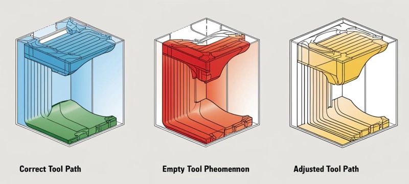
Fig. 4 kKnifetrack diagram
4. Selecting suitable printing materials
4.1 Using ABS material
In this example, the molding material chosen is ABS. Many people use ABS because it is one of the most widely used polymers. It has a high melting point and good thermoplasticity, and it is commonly used for 3D printing.
4.2 Adjusting Printing Parameters to Optimize Surface Quality
For 3D printing, the layering thickness of the model and how it is placed during the printing process greatly influence the surface roughness.
Studies have proven that using a certain layer thickness can improve surface quality. Printing the important molding surface as the top layer of the model enhances the surface finish.
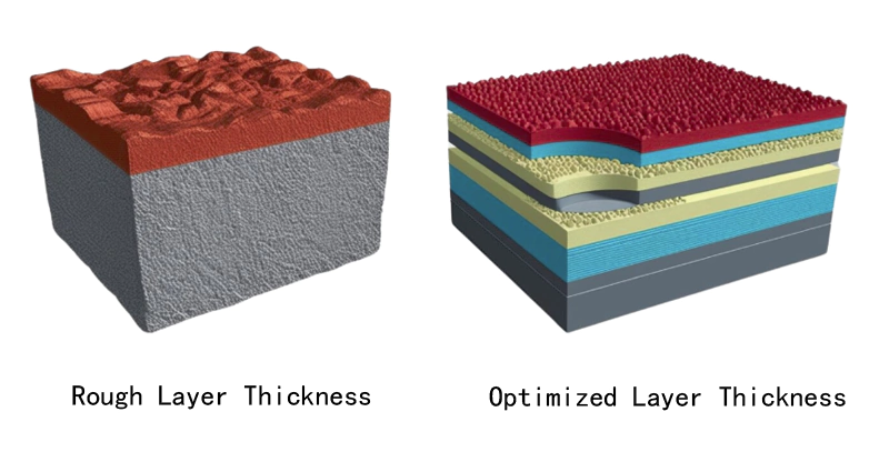
Fig. 5 Comparison of optimization of printing surface quality
5 . Post-printing processing
When you finish printing, remove the model and dissolve the support structure completely. Finally, you will obtain the generator end cover sample, as shown in Fig. 6.
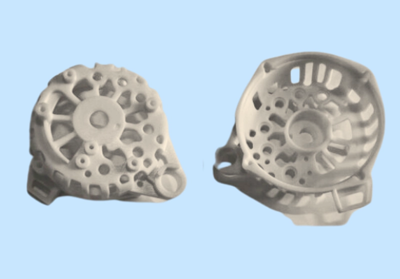
Fig. 6 Generator end cover sample
Conclusion
1. Advantages of rapid prototyping technology
Rapid prototyping manufacturing technology has significant time and cost advantages for manufacturing small-lot, single-piece products.
It is especially suitable for the rapid production of complex components. This technology significantly shortens the production cycle and reduces production costs.
2. Modeling technology in reverse reconstruction
When using forward and reverse hybrid modeling technology for the reverse reconstruction of porous complex parts, engineers should pay special attention to the boundaries of the model point cloud data.
The correct processing method is crucial, especially at the location of passivation and deep holes. Secondary forward design can significantly improve the accuracy of model reconstruction.
3. Accuracy control of casting structure end cover
We usually control the error for the model construction of cast structural end caps within ±0.5mm. We achieve this accuracy by optimizing the design and manufacturing process.
4. Trial production and verification of end cap prototypes
During the trial production of the end cap prototype, we can effectively improve the surface quality and strength of the product. You can achieve this by adjusting the placement of the end cap. Change the trajectory of the internal tool path.
This process validates the hybrid forward/reverse modeling method with the secondary forward design of special structures. This method can effectively improve the accuracy of model reconstruction.
5. Improve the design accuracy of porous complex structure components
The preparation of end cap samples can prove the method of joint use of forward/reverse hybrid modeling and secondary forward design.
It can improve the accuracy of model reconstruction and provide an effective design means for developing porous complex structural components.


