Table of Contents
In mechanical manufacturing, deep-hole and tiny deep-hole machining have been attracting a lot of attention. The diameter of small holes is generally 0.1 to 3.0 mm, and micro small holes are < 0.1 mm, while deep holes are those with a hole depth-to-hole diameter ratio > 10.
Based on the diameter, deep holes can be categorized as extra large, large, normal, small, and tiny deep holes. Usually, tiny deep holes and extra large deep holes are more difficult to machine.
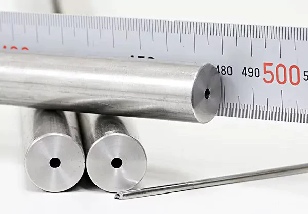
Tiny deep holes are widely used in aerospace, military, hydraulic valves, injector nozzles, and medical devices.
However, during the machining process, tool cooling and chip removal problems often lead to tool breakage, and traditional machining methods cannot help some difficult-to-machine materials.
In this paper, we will discuss the current micro deep hole machining methods, analyze their advantages and disadvantages, and look forward to future development, to provide a basis for further research.
Micro deep hole machining methods are divided into mechanical machining methods and special machining methods.
Mechanical machining methods mainly involve drilling, while special machining methods mainly include EDM, electrolytic machining, ultrasonic machining, laser machining, and electron beam machining.
Mechanical processing of tiny deep holes
The main machining method for tiny deep holes is drilling, known for its fast machining speed and wide range of applicable materials, making it a cost-effective choice.
Ordinary drilling is usually applied to holes with large diameters, small depth-to-diameter ratios, low molding accuracy, and low surface quality.
Drilling technology has also advanced with the development of material science and technology. In terms of equipment, high-speed motors and electric spindles are used.
Such as those from Fisher (Switzerland) and Forest-line (France), which have spindles up to 180,000 rpm.
At the same time, air-bearing and magnetic-bearing technologies have improved the rotational accuracy of spindles, such as the precision spindles of Japan’s NSK, which can reach 1 μm.
On the process side, drill sleeves guide the drill and allow step-by-step drilling to improve hole accuracy and depth.
Ultrasonic high-frequency vibration also improves tool stiffness and chip removal, enhancing machining quality and speed.
New materials and coating technologies, such as the MDSS-type carbide drills from Japan’s Jayo Electric, have a minimum diameter of just 30 μm and a maximum machining depth of 60 μm.
Deep hole machining is becoming increasingly complex, requiring a balance between chip removal and cooling to achieve optimal cutting conditions.
Beijing Aviation Precision Machinery Research Institute optimized the gun drill’s cutting-edge and cooling hole structure.
It developed an efficient machining method with a hole diameter of 2 to 10 mm and a depth-to-diameter ratio of 20 to 60, which improved the machining efficiency by more than 30%.
Regarding general material machining, drilling technology has significantly improved tool life and machining quality.
However, in terms of difficult-to-machine materials, the efficiency is low and costly, and some materials can not even be processed.
Special machining technology for tiny deep holes
This technology refers to the use of acoustic energy, electrical energy, thermal energy, light energy, chemical energy, and electrochemical energy.
Such as one or more kinds of energy composite, to realize the processing method of material removal.
Special processing micro deep hole methods mainly include electric discharge machining, electrolytic machining, ultrasonic machining, laser processing, and electron beam processing.
1. EDM micro deep hole processing
1.1EDM Micro Deep Hole Processing
Electrical Discharge Machining (EDM) uses pulse spark discharge between the tool and the workpiece. This discharge generates intense heat that removes excess metal. Fig. 1 shows the working principle.
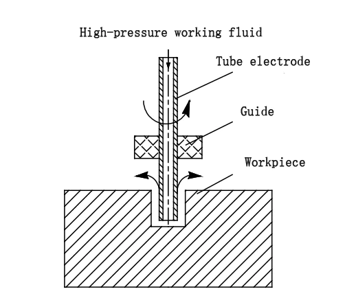
Fig 1 EDM micro deep small hole machining diagram
1.2Advantages of EDM Micro Deep Hole Processing
EDM offers several advantages over other machining methods:
(1)Processability of Any Conductive Material: EDM can process all conductive materials. This makes the process highly versatile.
(2)Variety of Hole Shapes: EDM can machine holes in various shapes and sizes. This makes it suitable for many applications.
(3)Low Strength and Stiffness Requirements for the Tool: The tools used in EDM micro deep hole processing require relatively low strength and stiffness. This reduces tool wear and increases process efficiency.
1.3Disadvantages of EDM Micro Deep Hole Processing
While EDM micro deep hole processing has benefits, it also has significant drawbacks:
(1)Thermal-Cast Layer: EDM uses thermal energy to remove metal. This process forms a thermo-cast layer on the machined surface. This layer can negatively affect the part’s service life and performance.
(2)Poor Hole Surface Quality and Machining Accuracy: EDM often results in lower surface quality and accuracy. It also creates a noticeable taper at the hole opening.
(3)Electrode Issues: The electrodes in EDM are prone to deformation and wear. This reduces machining efficiency.
Additionally, chip removal and heat dissipation are challenging. These issues hinder the widespread adoption of the process.
(4)Arc Pulling and Electrode Deformation: In typical EDM perforation molding, the small cross-sectional area of the electrode makes it prone to deformation.
Heat dissipation and chip removal are difficult, which causes arc pulling. This impedes normal processing.
Additionally, the electrode is fragile and prone to significant wear, reducing process stability.
(5)Depth-to-Diameter Limitation: The hole depth is generally limited. The typical depth-to-diameter ratio is about 20:1.
1.4Improvements in EDM Micro Deep Hole Processing
Several improvements have been made to overcome the limitations of traditional EDM perforation methods:
(1)Double-Hole Tubular Electrodes and Chipping Electrodes: Using double-hole tubular electrodes and chipping electrodes improves processing efficiency.
It also reduces taper and mitigates electrode loss issues. These innovations address the limitations of traditional EDM perforation.
(2)Workpiece Inverted Machining Mode: The workpiece inverted machining mode improves processing depth and stability. It allows for deeper and more precise hole processing.
2.15lobal Advancements in EDM Micro Deep Hole Machines
(1)Japan’s Matsushita Seiki EDM Machine: Matsushita Seiki in Japan developed EDM machines capable of stably processing micro-fine holes as small as 5μm.
These machines represent a significant advancement in EDM micro deep hole processing.
(2)Beijing Yitong Electric Processing Research Institute e: In China, the Beijing Yitong Electric Processing Research Institute developed a super-tiny deep-hole EDM machine.
This machine can process holes up to 2000mm in depth. It improves both machining efficiency and accuracy.
(3)China’s CNC High-Speed EDM Machines: China has reached internationally advanced levels in producing CNC high-speed EDM machines for small-hole processing.
These machines now exceed a depth-to-diameter ratio of 1000:1, setting a new benchmark for the EDM micro deep hole processing industry.
Electrolytic machining of small deep holes
1. Introduction to Electrolytic Machining
Electrolytic machining is a specialized method that relies on the principle of anode ion dissolution. It offers several advantages:
(1)Fast machining speed
(2)High surface quality
(3)A wide range of applications
This technique is commonly used in industries like aerospace, automotive, medical devices, and mold manufacturing.
1.1Challenges in Electrolytic Machining
Despite its advantages, electrolytic machining faces challenges. The process involves complex interactions between electrochemical, electric, and flow fields.
These interactions result in poor stability and machining accuracy. Additionally, the following limitations hinder broader use:
(1)High and expensive corrosion protection requirements for equipment
(2)Proper disposal of electrolysis products
1.2Types of Electrolytic Machining
(1)Micro deep hole electrolytic machining can be classified into two categories:
Electrolytic machining
Composite electrolytic machining
(2)Common methods in these processes include:
Electrochemical drilling
Cathodic electrolytic processing of molded tubes
Capillary electrolytic perforation
Most electrolytes used in these processes are acidic.
1.3Key Issues in Electrolytic Machining
In-molded tube cathodic electrolytic processing, the cathode surface is insulated to prevent corrosion. However, the main challenges include:
(1)Insulation issues
(2)Stray corrosion of the cathode
(3)Undesirable hole shapes, such as large taper
(4)Principle of Electrochemical Machining Holes
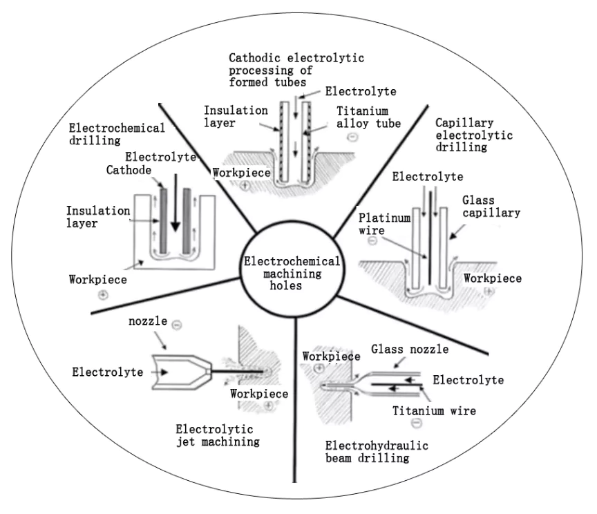
Fig. 2 Principle diagram of electrochemical machining holes
2. Advances in Electrolytic Machining Research
2.1Research by Prof. Di Zhu
Global research on electrolytic machining technology is growing. Prof. Di Zhu from Nanjing University of Aeronautics and Astronautics studied pressure distribution in electrolytic machining of tube electrodes.
He found that the voiding phenomenon in the machined area mainly resulted from changes in the electrolyte channel.
To solve this, he proposed using a translational electrode to remove the cavitation region, which improved machining stability.
2.2Research on Flow Fields and Electrolyte Behavior
Wang Wei and colleagues analyzed the flow field of a group-hole tube electrode. They discovered that reducing the number of cathodes or the inner diameter could make the flow field more uniform.
Moreover, wedge-shaped cathodes effectively improve flow field distribution.
2.3Improving Electric Field Distribution
Fang et al. worked on improving the electric field distribution in the machining gap. They adjusted the potential difference of the anode tube electrode to enhance machining precision.
Additionally, they used a pulsating flow field to improve the stability of tiny deep-hole machining.
3. Applications and Future Directions
3.1Electrolytic Machining for High-Temperature Alloys
The Indian Institute of Technology (IIT) studied electrolytic machining of nickel-based high-temperature alloys using a 1% HCl and NaCl mixed electrolyte.
They investigated variations in hole diameter and depth. They successfully machined bamboo cooling holes by adjusting the machining voltage and feed rate.
3.2Pulse Electrolytic Machining Tests
In a pulse electrolytic machining test at Warsaw University of Technology, Poland, the pulse interval time helped discharge electrolysis products. This improved machining stability. However, the efficiency was lower than that of the DC power source.
3.3Mathematical Modeling for Process Optimization
S. Hinduja and colleagues from the University of Manchester, UK, developed a mathematical model to analyze how processing voltage, feed rate, electrolyte pressure, and concentration affect hole diameter and taper.
This model is particularly useful for optimizing tube electrode processing in bamboo cooling holes.
3 . Ultrasonic machining of tiny deep holes
Ultrasonic machining is the use of ultrasonic vibration tools in a liquid medium with abrasive or dry abrasive material to produce abrasive impact, abrasive polishing, hydraulic impact, and the resulting cavitation to remove the material or the workpiece along a certain direction of the application of ultrasonic frequency vibration for machining, the machining schematic shown in Fig 3.
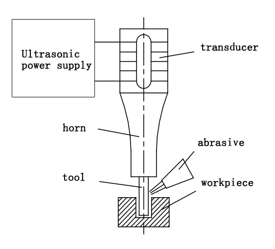
Fig 3 Ultrasonic machining of small deep holes schematic diagram
Extensive research on ultrasonic machining technology has been carried out worldwide. For example, the Beijing University of Aeronautics and Astronautics found that rotary ultrasonic machining is significantly better than conventional drilling regarding material removal rate and surface quality when processing carbon fiber-reinforced plastics, while tool loss is reduced.
The Dalian University of Technology used an end chamfering tool to process potassium dihydrogen phosphate crystals with good results. Tianjin University has improved the efficiency and quality of processing small holes in engineering ceramics by driving tools through electromagnetic conversion technology.
Harbin Institute of Technology has processed 13μm micro-holes on silicon wafers and combined ultrasonic and EDM machining to realize efficient machining of small-diameter deep holes in titanium alloys.
Nanjing University of Aeronautics and Astronautics researches ultrasonic EDM and electrolytic composite machining, which significantly improves machining efficiency and quality.
Kansas State University established a rotary ultrasonic machining mathematical model. Indian scholars have also achieved good results in the n ultrasonic machining of titanium alloy. Swiss scholars have found that the twist drill tool is more efficient in tiny deep-hole machining.
4. Laser processing of small deep holes
Laser processing of small deep holes uses light energy by focusing the system at the focal point to reach a very high energy density, so that the instantaneous material melting, vaporization, and melting and vaporization of the explosive jet in the workpiece after the formation of small deep holes, as shown in the processing schematic in Fig 4.

Fig 4 Laser processing of small deep holes schematic diagram
Compared with traditional mechanical processing methods, laser processing of small deep holes with fast processing speed, high efficiency, and small heat-affected zone, etc., is suitable for a variety of materials processing, the minimum hole diameter of the processed holes is up to 4 ~ 5 μm, the depth ratio of up to 10 or more.
Such as the Demagi DML series laser processing center, the output power of up to 10 ~ 20kW, the surface roughness of the processed parts for Ra1μm, the material removal rate of up to 25m/min, the minimum diameter of the processed hole for 5μm, 20mm deep;
However, in general, the surface roughness of the processed hole is large, the roundness is relatively poor, and it is easy to form a flare mouth, it is necessary to reduce the flare mouth by an additional optical control axis, and the accuracy of the hole is generally lower than the IT8 level, and at the same time the high price of the laser equipment has also limited its application.
The global research on laser processing is mainly focused on the following 2 aspects.
4.1 shorten the laser pulse width and increase the peak power.
Femtosecond laser processing so that the thickness of its recast layer is reduced, and its thickness can generally be controlled at 0.02 ~ 0.05mm, the high energy density deposits produced within an instant will make the absorption of electrons and the way the movement is altered with ultra-high precision, spatial resolution and wide range of non-thermal fusion treatment process.
Germany Hanover laser center using 150 fs, high energy density of femtosecond laser in 1mm(see Fig 5).
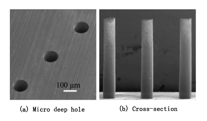
Fig 5 Femtosecond laser processing of small deep holes Fig
4.2Eliminate micro-cracks, recast layer
Laser composite processing mainly includes jet gas-assisted laser processing, underwater laser processing, water-guided laser processing, chemical-assisted laser processing, ultrasound-assisted laser processing, etc., which can significantly improve the processing quality and reduce the micro-cracks, recast layer, and heat-affected zone.
Xi’an Jiaotong University Mei Xuesong et al. precisely controlled and removed the laser-processed microcooling hole recasts and reduced the thickness of recasts to less than 5 μm by optimizing the laser process parameters. The processed small holes without the recast layer are shown in Fig. 6
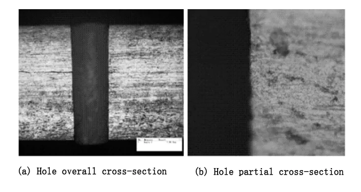
Fig. 6 Optical microscope view of the hole as a whole and local section
5. Electron beam machining of tiny deep holes
Electron beam machining converts the kinetic energy of electrons into thermal energy by using high-speed electrons to impact the workpiece. When a metal is heated in a vacuum, electrons escape from the atoms and form a high-speed beam of electrons.
This beam of electrons, focused by a magnetic lens, has an extremely high energy density and instantly raises the surface temperature of the workpiece to several thousand degrees Celsius, causing localized melting and vaporization of the material, resulting in the formation of holes.
This drilling method is highly efficient, with tens of thousands of holes per second, and good quality with virtually no flying edges or heat-affected layers. By controlling the speed of the electrons and the strength of the magnetic field, it is possible to achieve precise curved holes inside the workpiece.
At present, the minimum diameter of electron beam hole punching can reach 0.003mm, the depth-to-diameter ratio of the hole can be up to 100:1, and the inner slope is about 1°~2°, which is suitable for jet engine cooling holes and wing adsorption screen holes and so on.
Electron beam processing in a vacuum environment causes less pollution and no oxidation of the surface, which is especially suitable for materials prone to oxidation, especially high-purity semiconductor materials.
However, due to the high requirements of the equipment in the vacuum environment, the system cost is high, which limits its wide application.
With the advancement of science and technology and the emergence of new materials, the processing of tiny deep holes in the future will rely more and more on composite processing methods, such as ultrasonic vibration drilling, electrolytic-mechanical composite processing, and so on.
Table 1 Analysis of micro deep hole machining methods
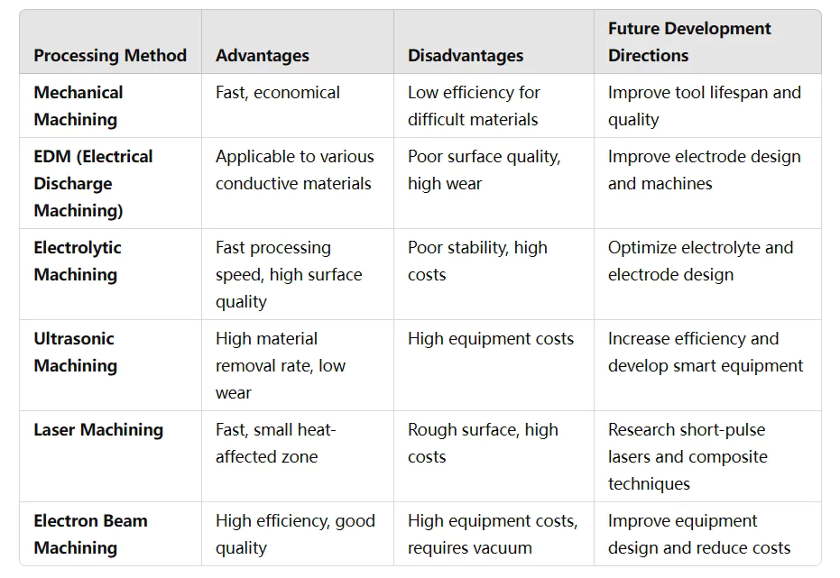
Micro deep hole machining technology development trend
With the development of science and technology, and the emergence of new materials, the future precision machining of tiny deep holes is difficult to realize through a single processing method, the composite processing method is bound to become the development trend.
Composite processing mainly has ultrasonic vibration drilling, electrolytic mechanical composite processing, electrolytic EDM composite processing, electrolytic laser composite processing, and ultrasonic electrolytic composite processing.
1. Ultrasonic vibration drilling tiny deep holes
Ultrasonic vibration drilling is mainly drilling, and ultrasonic vibration is a complementary composite processing.
By applying ultrasonic high-frequency vibration to the drill bit, the drill bit and the workpiece produce a periodic separation between the cutting force changes periodically.
At the same time, the rigidity of the tool has also been improved.
The main modes of drill vibration are axial vibration, torsional vibration, and axial-torsional compound vibration (see Fig 7). In the process, ultrasonic high-frequency vibration drilling from continuous cutting to intermittent cutting improves the chip breakage and chip removal, cooling, and heat dissipation conditions, the formation of the pulse torque greatly reduces the friction factor between the drill bit and the workpiece, chips, reducing the drilling force, improving the service life of the drill bit and the quality and efficiency of the processed surface.
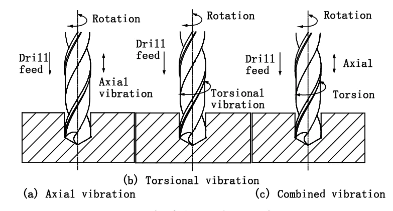
Fig 7 Ultrasonic vibration drilling schematic
Prof. Zhang Deyuan from Beijing University of Aeronautics and Astronautics and Zhao Bo from Henan University of Technology developed an ultrasonic vibration drilling test bench, which can adapt to different shapes and thicknesses of workpieces to realize ultrasonic-assisted drilling processing.
The study shows that ultrasonic vibration can improve the crack toughness of SiC particle-reinforced aluminum matrix composites, enhance the surface roughness, and reduce the chipping phenomenon.
A comparative study by VARUN showed that ultrasonic vibratory cutting has lower cutting forces and tool wear than conventional cutting, with surface quality down to the nanometer scale.GHLANI et al. successfully drilled deep holes in nickel-based alloys and found that lower spindle speeds can reduce axial forces and improve surface quality.
For new materials such as carbon fiber composites and titanium alloys, ultrasonic vibratory drilling can effectively reduce the axial force of the drill bit and lateral cutting force, thus reducing tool wear and improving the hole’s accuracy.
2. Electrolytic mechanical composite processing of tiny deep holes
Electrolytic mechanical composite machining mainly uses mechanical action to remove the passivation film produced in the electrolysis process. Therefore, electrolytic machining is a composite machining technology mainly based on electrical machining, with mechanical machining as a supplement.
Figure 8 shows a typical electrolytic grinding machining schematic.
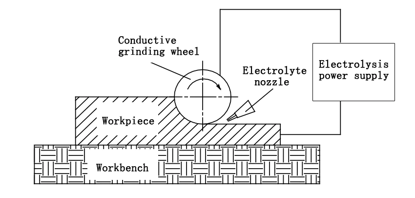
Fig 8 Schematic diagram of electrolytic grinding processing
Nanjing University of Aeronautics and Astronautics and Changzhou Institute of Technology conducted a series of studies on electrolytic grinding, the overall impeller blade profile five-axis linkage CNC spreading electrolytic grinding machining mechanism research, the overall impeller polishing efficiency increased by 12 times, solved the overall impeller blade profile finishing technical problems.
Professor Zhu Yu and others applied electrolytic grinding to finishing. They optimized the process parameters of electrolytic grinding on the processed small holes (see Fig. 9), which can meet the requirements of fuel nozzles.
The introduction of mechanical action in the process of electrolytic machining, greatly improving the efficiency of electrolytic machining, has been widely used in large rolls, and large chemical container-shaped cavity polishing.
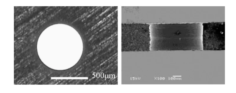
Fig 9 Optimal process parameters under the processing of the hole
3. Electrolytic EDM composite processing of small deep holes
Electrolytic EDM composite machining takes full advantage of the higher molding accuracy of EDM and electrolytic machining of better surface quality characteristics in the same processing station, using different tools electrodes, first EDM molding process, and then electrolytic machining to remove the EDM generated recast layer, processing schematic shown in Fig 10.
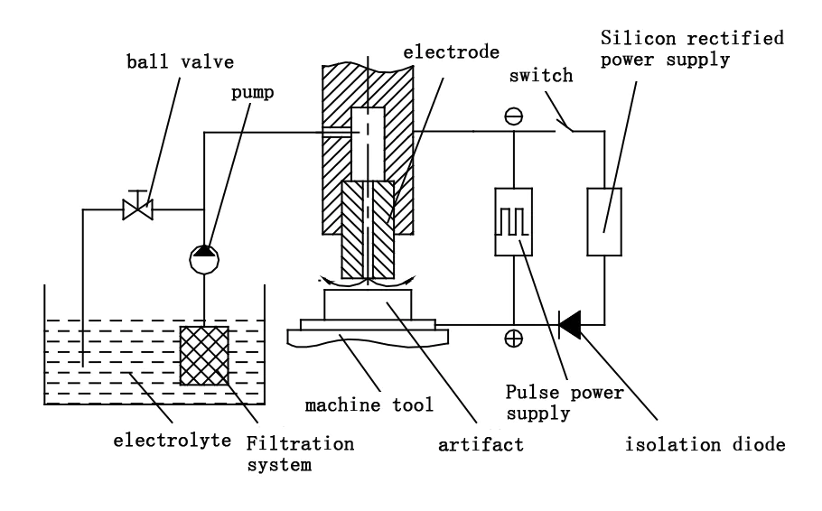
Fig 10 Electrolysis – EDM composite machining diagram
Electrolytic EDM composite machining technology integrates the advantages of EDM and electrolytic machining while making up for their shortcomings.
EDM has a higher machining accuracy and is suitable for the processing of difficult-to-machine metal materials, but there is a recast layer on the surface of the processing;
Electrolytic machining has good surface quality, high processing efficiency, no tool loss, no cutting stress, the advantages of the recast layer, etc., but it is difficult to mold accuracy to a high degree of precision.
Combining these two machining processes can achieve high accuracy and surface quality by utilizing their strengths and avoiding their weaknesses.
South Korea, Yonsei University ultrasonic electrolytic EDM composite processing deep hole test, single-ended insulated electrodes can increase the depth-to-diameter ratio of the hole Baza et al. first deionized water solution for EDM.
Then, the liquid will be replaced by an electrolytic solution containing phosphoric acid, electrolytic polishing of the micro-hole to remove the recast layer, to get the micro-hole without a recast layer, and the processing effect shown in Fig. 11; its processing results.
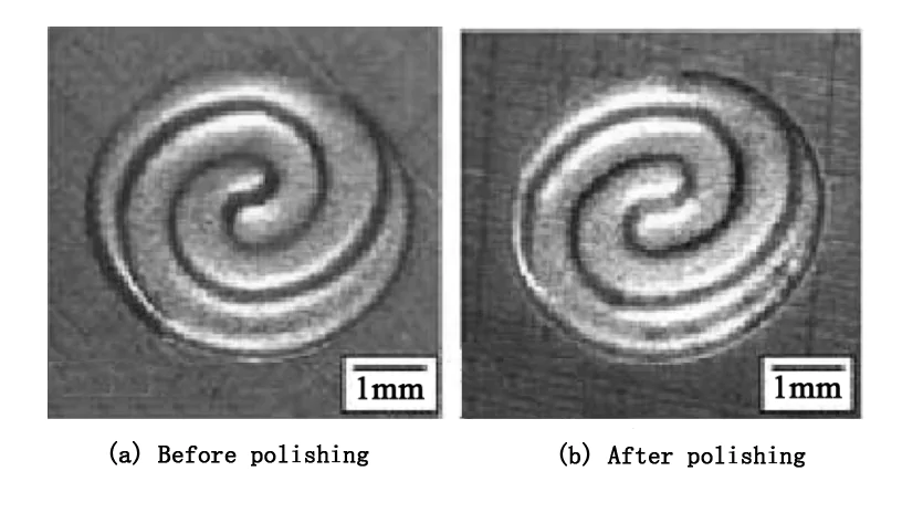
Fig 11 Electrolysis – EDM polishing processing effect diagram
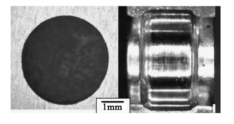
Fig 12 Electrolysis – EDM grinding effect diagram
However, due to discharge and cathode loss, the technology is still in the experimental research stage, and the processing mechanism and process research are not deep enough.
4. Electrolytic laser composite processing of tiny deep holes
In electrolytic jet processing, the laser east in the jet electrolyte beam under the guidance of total reflection through the jet removes the material, while the region of the electrolyte local temperature increases, improving the efficiency of electrolytic jet processing and electrolytic jet processing of the domain.
A laser beam of efficient processing reduces the taper of the processed hole, increasing the depth-to-diameter ratio.
Electrolytic jet processing will also be produced by laser processing of recast layer, residual stress and micro-cracks, and other defects, “online” removal, the two composite, not only to maintain the surface quality of the electrolytic jet machining is good, but also take full advantage of the high efficiency of the laser machining features, to make up for the shortcomings of the respective processing. The respective processing of the deficiencies that exist. Processing schematic diagram as shown in Fig 13.
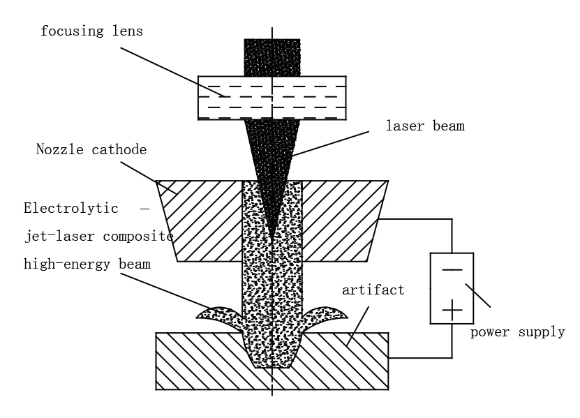
Fig. 13 Schematic diagram of electrolytic jet-laser composite processing
The technical research on laser-assisted jet electrolytic processing conducted by Prof. P.T. Paiak of the University of Scotland, Glasgow, shows that introducing laser assistance improves the precision and efficiency of electrolytic processing.
At the same time, the surface is free of recast layer, residual stress, and microcracks.
Nanjing University of Aeronautics and Astronautics on the electrolytic jet laser-assisted processing of the hole surface quality and processing efficiency of the basic process research shows that the electrolytic jet laser composite processing can effectively remove the laser processing of the recast layer and spots produced by the processing of the surface of the holes without a heat-affected zone, as shown in Fig 14.
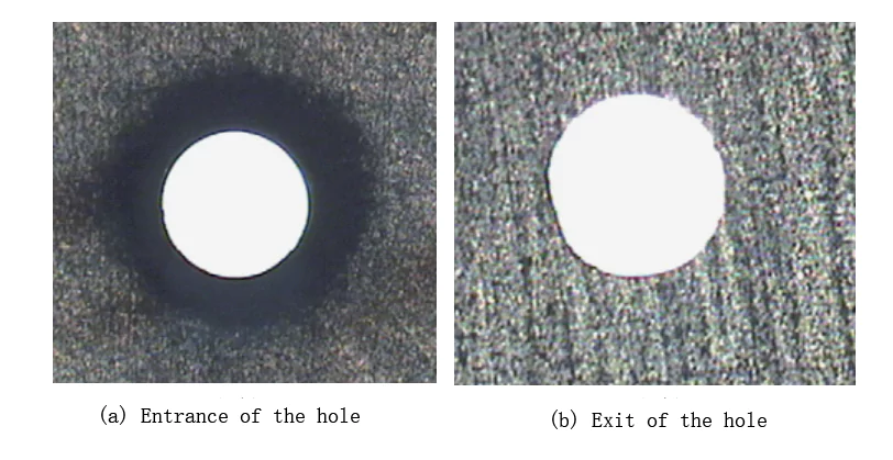
Fig 14 Electrolytic jet-laser composite processing of holes in the effect of the map
5. Ultrasonic electrolytic composite processing of small deep holes
5.1.Introduction
Electrolytic machining often encounters problems due to the formation of passivation films. These films hinder the process. Common methods to remove them include:
Using high current density
Applying high electrolyte pressure
However, these methods raise machining costs and lower quality and accuracy. Linear electrolytes can also cause stray corrosion, which further affects part quality.
Combining Ultrasonic and Electrolytic Machining
Ultrasonic machining improves accuracy and surface quality, though it has lower efficiency. Combining ultrasonic and electrolytic machining provides several benefits:
(1)High-frequency vibration and cavitation effectively remove the passivation film.
(2)Periodic changes in electrolyte pressure and flow refresh the electrolyte and remove products.
(3)Adding fine abrasives to the electrolyte increases processing speed and surface quality.
During this process, the cathode vibrates ultrasonically and moves toward the anode at a controlled speed. This vibration breaks the passivation layer and reactivates the anode surface.
Processing Mechanism and Schematic
The alternating passivation and activation states significantly boost processing speed.
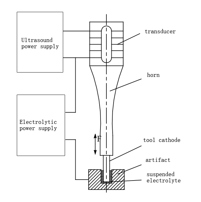
Fig 15 Schematic of ultrasonic electrolytic composite processing
5.2Advances in Ultrasonic Electrolytic Machining Research
Improvements in Surface Quality
A. Ruszaj and colleagues from Poland’s Institute of Advanced Manufacturing Technology improved surface quality with ultrasonic electrolytic machining. They achieved the best results by adding abrasive powder.
S. Skoczypiec and his team analyzed the electrolyte flow using simulations. They found that ultrasonic vibration alters air pocket pressure and intensity.
Proper vibration amplitude reduced electrode polarization and improved machining.
Effects of Low-Frequency Vibration
B. Bhattacharyya demonstrated how low-frequency vibration (150–200 Hz) increases material removal rates and machining accuracy.
Compared to high-frequency vibration, low-frequency vibration better discharges products.
M. S. Hewidy created mathematical models to study low-frequency vibrations. He discovered that vibration amplitude and machining gap directly affect the tool service life.
5.3Microfabrication and Technical Advantages
Application in Microstructure Processing
Research from Nanjing University of Aeronautics and Astronautics and Yangzhou University confirmed that ultrasonic electrolytic composite processing works well for microstructure machining.
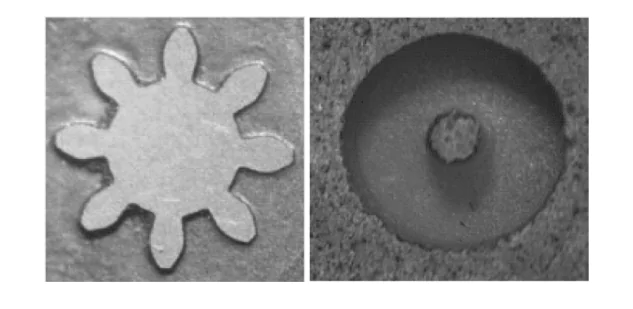
Fig 16 Ultrasonic electrolytic composite microfabrication micro components
Rotary Ultrasonic Electrolytic Composite Machining
Nanjing Agricultural University explored rotary ultrasonic electrolytic composite machining for tiny deep holes.
They developed a device with internal electrolyte spraying. Their findings included:
Simulated flow and electric fields optimized the process.
Rotary ultrasonic machining delivered better quality and stability compared to rotary electrolytic machining.
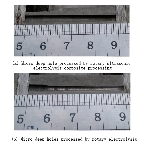
Fig 17 Comparison of 2 ways of machining tiny deep holes
Advantages of Ultrasonic-Assisted Machining
Rotary ultrasonic electrolytic composite machining outperforms rotary electrolytic machining under the same parameters. Key benefits include:
(1)Significant improvements in machining quality for tiny deep holes
(2)Enhanced stability due to ultrasonic high-frequency vibration
(3)Increased machining depth by using a guide sleeve to guide the tool cathode
5.4Development Trends in Micro Deep Hole Machining
Micro-deep hole machining technology continues to evolve. Researchers are working to enhance speed, precision, and surface quality. Table 2 outlines the key trends shaping future innovations.
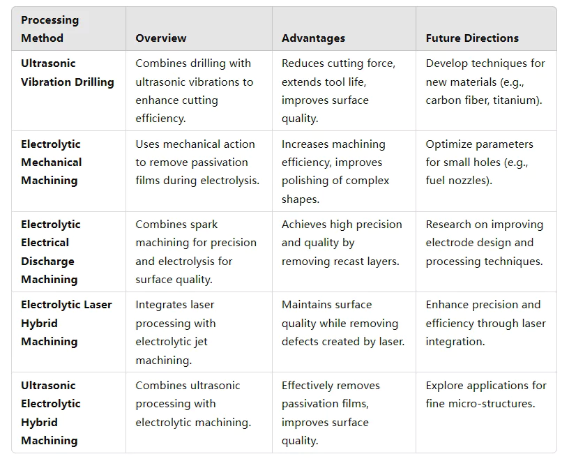
Table 2 Development trend of micro deep hole machining technology
Conclusion
With the progress of science and technology, difficult-to-machine materials and new types of materials are emerging, and the requirements for machining methods are increasing.
Hole parts are widely used in the mechanical industry. Future precision machining of tiny deep holes will no longer rely on a single method but on composite machining technology to improve machining accuracy and efficiency.
This paper briefly reviews the current situation of tiny deep hole machining, introduces the basic principles of traditional special machining and its elopement dynamics, and proposes combining vibration or electrolytic machining with other methods to form a composite machining technology to compensate for their respective shortcomings, thus promoting the development of the future remanufacturing industry.


