
However, the cost of manufacturing electrodes during the EDM process is high, and they are easy to wear.
At the same time, using kerosene as the working fluid also has safety hazards and pollution problems.
Advances in machine tools and tool technology have enabled direct processing of hard-to-handle materials through cutting.
High-speed milling technology, in particular, has increasingly replaced traditional EDM methods.

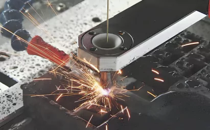
Electrical discharge machining diagram
In the 1990s, researchers proposed a three-dimensional CNC EDM milling method.
This technology scans layers using simple rod-shaped electrodes. It reduces processing costs and improves flexibility. However, it also causes environmental pollution.
Professor Masanori Kunieda from Tokyo University of Agriculture and Technology introduced dry electric discharge milling. He replaced traditional kerosene fluid with gas as the dielectric.
The researchers observed that gases can remove materials at rates comparable to or better than kerosene working fluids when conditions are optimized.
Experimenters of in-gas EDM milling demonstrated that EDM in oxygen achieves higher material removal rates than kerosene operating fluids.
In-air machining increases dimensional accuracy. This happens as the electrode rotates during the process.
Molten workpiece material splashes onto the electrode during gas processing. This compensates for electrode loss and can even lead to negative loss.
The study showed that gas machining creates larger, shallower electric corrosion pits. It forms a thinner white layer on the workpiece surface and results in better surface quality.
In-gas EDM progress
Masanori Kunieda believes in-gas EDM offers two key advantages. It creates minimal reaction force. It also causes minimal surface damage to the workpiece. These features make it ideal for micromachining. Kunieda also studied wire electrical discharge cutting in gas (DRY-WEDM).
Zhang Qin and his team from the Institute of Manufacturing Automation of Shandong University developed a new processing method. This method combines dry electric discharge machining with ultrasonic vibration applied to the workpiece.
Powder mixing, fluid bubbles
The Special Processing Research Institute of Harbin Institute of Technology studied the processing characteristics of the powder mixing working fluid. After that, they attempted to mix gas into kerosene for processing.
The results indicate that adding gas to the working fluid increases processing efficiency. It also improves surface quality to some extent.
Mixing uniform fine bubbles into kerosene remains a significant challenge. In kerosene, bubbles easily diffuse and aggregate. This behavior is particularly evident on the electrode surface, where it affects the discharge effect.
This method also poses risks of environmental contamination.
To address these issues, researchers explored new working fluids. They focused on water-based working fluids as alternatives.
Comparative experiments revealed that pure water working fluids generally remove material at a lower rate compared to kerosene-based fluids with organic compounds.
Adding organic substances such as polyethylene glycol or glycerin to water-based fluids enhances the removal rate.
However, using water-based fluids increases machine tool costs. Their disposal costs are similar to those of kerosene-based fluids.
In addition, water-based non-combustible fluids raise equipment operation costs. These costs are higher than those of regular kerosene fluid systems. As a result, large-scale adoption of this method is difficult.
EDM milling in oxygen
Spray EDM milling proposal.
In EDM, we aim to improve efficiency and quality. At the same time, we focus on reducing manufacturing costs and dependence on working fluid.
To achieve this, researchers need to explore new methods. These methods should maximize EDM’s advantages and minimize its environmental impact.
After analyzing previous research results, we developed a new method called “mist-jetting-ED-milling.”
Figure 1 illustrates the processing principle. It includes the following components:
(1) workpiece, (2) pulse power supply, (3) automatic feed adjustment device, (4) tool, (5) working fluid, (6) filter, and (7) working fluid pump.
This method uses high-pressure mist as the discharge medium. The mist is created by mixing water and gas. It combines the benefits of dry EDM milling, liquid EDM, and CNC EDM while addressing their limitations.
Its core elements can be described as:
(1) Use high-pressure water mist as the working medium.
(2) Use simple-shaped hollow tubular electrodes.
(3) Adopt layered scanning CNC EDM milling processing strategy.

Figure 1 Principle diagram of spray EDM
Spray EDM mechanism analysis
The discharge medium is one of the three major elements of EDM: discharge medium, electrode material pair, and pulse power supply.
Significant changes in the discharge medium have occurred. These changes directly affect the core of EDM, which is the mechanism of the discharge process.
We need to revisit and understand fog electric discharge machining characteristics. This should be done based on the existing understanding of the electric discharge machining mechanism.
The following sections analyze the various processes and attributes of EDM in a fog medium.

Three major elements that constitute EDM
1. Breakdown voltage channel formation
So far, electrical machining experts inside and outside China have not reached a unified conclusion.
They are still debating the dielectric breakdown process and how discharge channels form during EDM.
Research on the mechanism of spark discharge is generally based on dielectric physics.
It focuses on two aspects: the discharge mechanism in pure dielectric media (gas and liquid) and the discharge mechanism in liquids containing additives.
Discharge with additives includes powder mixing, gas mixing, and EDM milling. All these processes fall under the category of additive discharge.
The electric field distorts during these processes, which changes the breakdown field strength. In most EDM scenarios, the gas phase remains continuous, while the liquid phase is dispersed.
When droplets mix into the gas, they change the shape of the electric field. Assuming the electric field between the two poles is uniform, Gauss’s law can help estimate the effect.
The maximum electric field intensity on a droplet surface is about 3 times stronger than usual because air and water have dielectric coefficients of 1 and 80, respectively.
During spark discharge in a foggy environment, the breakdown voltage drops significantly. It reduces to about one-third of the breakdown voltage in pure gas.
As a result, the discharge gap in the fog is much larger than in the gas. This allows the use of larger machining gaps.
A larger gap ensures a more stable discharge and reduces the chances of short circuits.
Therefore, in fog, the breakdown voltage and discharge gap adapt to enable more efficient machining processes.
2. Discharge channels, pit size
When performing EDM in fog, the working medium is a two-phase fluid created by mixing gas and liquid.
During discharge, the plasma channel does not experience the inertial compression caused by a liquid medium. This is different from the compression in liquid-based discharge.
The magnetic field generated by the current provides the only resistance to the expansion of the discharge channel.
At the beginning of the discharge, the channel cross-section expands faster than in liquid machining.
(1) Better surface quality: The discharge channel in the mist has a larger cross-section compared to liquid discharge.
This generates large and shallow electric corrosion pits during processing. These pits help achieve better surface quality.
The surface produced during processing has a thinner white layer. It also has lower surface roughness, which is especially useful in milling.
(2) Lower throwing force: Liquid does not compress the channel. As a result, the force generated during discharge is smaller.
This allows the use of a smaller processing gap than in liquid discharge. Alternatively, greater discharge energy can be applied to improve efficiency.
3. Deionization in the discharge channel
At the start of pulse discharge during liquid discharge machining, the plasma channel expands due to the liquid’s inertia. The discharge channel stays in a bubble state for a short period.
Complete deionization requires enough pulse interval time.
During fog discharge machining, the discharge channel lacks liquid inertia. Heated liquid droplets in the fog vaporize and absorb heat. This process helps the plasma warm quickly and deionize rapidly.
The vaporization process also causes plasma fluctuations. These fluctuations further shorten the deionization time. This allows for the use of higher pulse frequencies.
4. Erosion of electrode material
During EDM milling in the fog, the plasma heats the droplets. This heating vaporizes the droplets and expands their volume more than 1,000 times.
This process creates an explosion-like effect. The strong impact force directly strikes the tool electrode’s surface. This impact throws metal into the molten pool.
Additionally, the vaporization of droplets causes the plasma to fluctuate. These fluctuations strengthen the magnetic fluid oscillation. They also promote metal discharge in the electrode’s molten pool.
The tool electrode ejects high-pressure mist. This mist cools the metal electrode. It also reduces the tool electrode’s erosion during discharge. As a result, the tool electrode experiences less relative loss.
Feasibility test
The team modified the existing TROOP-PNC EDM forming machine to verify the feasibility of spray EDM milling. They then carried out a feasibility verification test.
Internal spray EDM uses a hollow electrode
Therefore, the machine tool has been modified as follows:
(1) Change the clamped-shaped electrode to a hollow replaceable tubular copper electrode.
(2) Use siphon nozzles to generate high-pressure mist.
(3) Close the working fluid system.
(4) Adopt a processing method similar to layer milling. Figure 2 shows a physical photo of the modified machine tool spray device and electrodes.

Figure 2 Actual photos of the spray device and electrodes
In this test, the compressed air pressure used was between 0.4~0.8MPa.
The specially made siphon nozzle ensures that the droplet diameter does not exceed 20μm. This prevents the droplet diameter from being too large in the processing gap, which could cause discharge in the liquid.
The tool electrode consists of a copper tube. The tube has an outer diameter of 9 mm, an inner diameter of 6 mm, a length of 10 mm, and a wall thickness of 1.5 mm.
If the electrode wall thickness is too thin, it will affect the processing efficiency.
At the same time, if it is too thick, the mist medium will not be evenly distributed on the electrode surface.
The test parameters are shown in Table 1.

Table 1 Spray EDM milling test parameters and results
The SEM photo of the processed surface is shown in Figure 3.

Figure 3 SEM photo of the workpiece surface after processing
The waveform during processing is shown in Figure 4.

Spray EDM milling is feasible
The following phenomena can be initially observed during the test:
(1) Spray processing results in lower surface roughness than oil processing with the same electrical parameters.
(2) The electric corrosion pit diameter is larger on the surface processed by fog than in oil.
(3) Fog machining can achieve a low short-circuit rate even without modifying circuits or rotating electrodes.
(4) The efficiency of this mist processing test is lower than that of oil processing.
Conclusion
Developing a dedicated power supply and control system for fog processing can increase the material removal rate and reduce electrode loss.

