In the programming and practical operation of beginners, they often struggle to distinguish between forward and reverse milling.
As a result, they may not be able to correctly determine when to choose the forward or reverse milling machining method.
Circumferential milling in smooth milling and reverse milling does not correspond to the machine tool’s spindle rotation and reversal.
Instead, it is determined by the direction in which the milling cutter teeth enter the material.
This paper analyzes the direction of the incision and the direction of the cutting force during forward and reverse milling.
It also illustrates the relationship between forward and reverse milling and the tool path through practical examples.
Discover the effects of forward and reverse milling on the machining quality of the workpiece, the life of the machine tool and the tool.
For beginners in the milling process when how to choose the smooth milling and reverse milling to provide a basis and help.
Distinction between forward and reverse milling
1. Distinguish from the direction of cutting teeth
In the milling machine, the process of milling involves using teeth distributed along the circumference of a cylindrical milling cutter.
This method is used to process parts and is called the circumferential milling processing method.
You can analyze the difference between downstream milling and reverse milling by considering two factors.
First, the direction in which the teeth cut into the material. Second, the trajectory of the milling cutter relative to the contour of the workpiece.
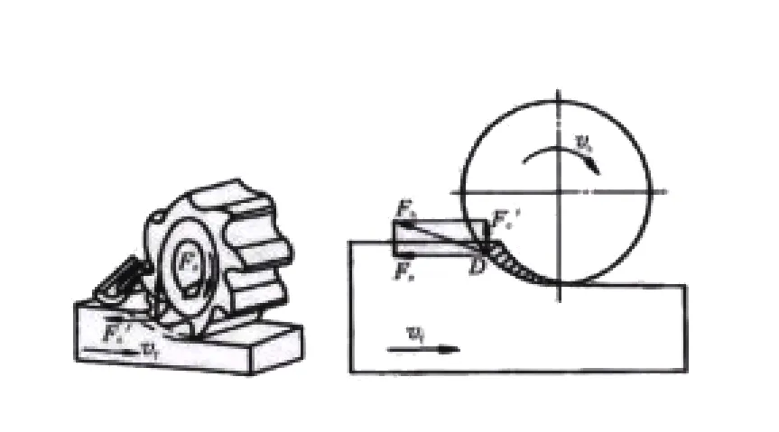
(1) As can be seen from Figure 1, the direction of rotation of the milling cutter is the same as the direction of movement of the workpiece.
Let’s say, on a treadmill, people run forward, running belt moving backward.
From Figure 1, we can see that the teeth are not machined from the surface. Instead, the teeth cut into the material from the top to the bottom.
The cutting into the material progresses from thick to thin. This cutting and processing method is called smooth milling.

(2) can be seen from Figure 2, the direction of rotation of the milling cutter and the direction of workpiece movement is exactly the opposite.
Let’s say, on a treadmill, people run forward, running belt moving forward.
From Figure 2, we can see that the teeth are cut from the machined surface. The teeth cut from the bottom to the top of the material.
The cutting into the material progresses from thin to thick. This cutting process is known as reverse milling.
2. Distinguish from the trajectory of the milling cutter
In the actual teaching process, beginners often have difficulty distinguishing between spindle rotation, reversal, and their relationship with smooth milling and reverse milling.
They frequently assume that spindle rotation is smooth milling and spindle reversal is reverse milling.
Spindle rotation and reversal are determined based on the milling cutter’s thread rotation.
For a right-threaded milling cutter, the rotation in the machine tool can only be positive.
For a left-threaded milling cutter, the rotation in the machine tool can only be reversed.
(1) When the CNC machine tool uses an end milling cutter to process the outer contour of the part, a right-threaded end milling cutter is selected.
The spindle is rotated positively, and the milling cutter rotates in a clockwise direction.

From Fig. 3A, the forward direction of the milling cutter relative to the workpiece is clockwise milling along the outer contour of the workpiece.
This machining method is known as smooth milling.
From Fig. 3B, the milling cutter advances relative to the workpiece in the direction of counterclockwise milling along the contour of the workpiece.
This milling method is called counter milling.
When an end mill is selected with a left thread rotation and the spindle is reversed, the milling cutter rotates in the counterclockwise direction.
As shown in Fig. 3A, the milling cutter advances relative to the workpiece in the direction of clockwise milling along the outer contour of the workpiece.
This milling method is known as counterclockwise milling.
From Figure 3B, the milling cutter moves relative to the forward direction of the workpiece.
It follows the contour of the workpiece and performs counterclockwise milling. This method is known as smooth milling.
(2) When the CNC machine tool adopts an end milling cutter to process the inner contour of the part, the end milling cutter with right thread rotation is selected.
The spindle rotates positively, and the rotating direction of the milling cutter is clockwise.
From Figure 3C, the forward direction of the milling cutter relative to the workpiece is along the inner contour of the workpiece.
This milling method, which involves counterclockwise milling, is known as smooth milling.
From Fig. 3D, the milling method involves the milling cutter advancing relative to the workpiece.
This movement occurs in the direction of clockwise milling along the inner contour of the workpiece. This method is known as counterclockwise milling.
When an end mill is selected with a left thread rotation and the spindle is reversed, the direction of rotation of the milling cutter is counterclockwise.
From Fig. 3C, the milling cutter advances relative to the workpiece in the direction of counterclockwise milling along the outer contour of the workpiece.
From Fig. 3D, the milling method involves the milling cutter advancing relative to the workpiece.
This movement occurs in the direction of counterclockwise milling along the outer contour of the workpiece. This method is known as smooth milling.
Application of forward and reverse milling
1. Rough and finish machining
When roughing the material, the surface of the workpiece is uneven.
Additionally, the surface may be hardened to some degree due to oxidation from contact with the outside environment.
In the case of the downstream milling method, the teeth of the milling cutter are cut from the unprocessed surface of the workpiece.
The unevenness and high hardness of the surface can damage the milling cutter and shorten the tool life.
When roughing, the surface finish quality of the workpiece is required to be low, so try to use reverse milling when roughing.
When finishing the workpiece, the surface is already relatively smooth and free of hard skin.
At this point, in order to reduce burrs, improve machining accuracy, and decrease the roughness of the surface, the processing method of smooth milling is used.
2. From the processing material
(1) For milling cast iron or hard materials with high surface roughness, it is important to avoid the cutter teeth continuously cutting into the hard surface.
To prevent this and avoid damaging the tool, reverse milling should be used.
In ordinary milling machine processing, when milling materials with surface hardness, the worktable may move.
However, in reverse milling, when processing materials with surface hardness, the worktable will not move.
(2) Milling of low-carbon steel, aluminum alloy, and other materials with low hardness should produce a more uniform cutting force.
This helps ensure that the table will not move during the process.
In ordinary milling machine processing, you can choose either downstream milling or reverse milling.
Both methods can be used to process materials with lower hardness.
3. From the tool life points
As can be seen from Fig. 1, the teeth of the milling cutter will not come into contact with the machined surface from the time it cuts into the part to the time it comes out.
From Figure 2, we can see that the teeth cut into the part from the machining surface.
Before the teeth cut into the part, they will slide on the machined surface for a certain distance.
The sliding of the teeth on the machined surface causes intense friction.
This friction generates a lot of heat. The heat not only hardens the surface to be machined, but it also shortens the life of the tool due to the high temperature.
Therefore, from the point of view of high tool service life, try to use smooth milling processing method.
4. From the cutting allowance to points
(1) When milling in the downward direction, the cutter teeth cut from the top to the bottom.
This generates a downward force, which presses the workpiece. This pressure is favorable for machining.
In reverse milling, the cutter teeth cut from bottom to top.
This creates an upward force, which can lift the workpiece on the table.
As a result, the clamping of the workpiece becomes unfavorable, potentially affecting the processing.
When the rigidity of the spindle of the machine tool is not calculated, the milling process requires more than just calculating the cutting force.
It also needs to consider the machine clearance and the machine tool’s cutting process.
Additionally, the tool force produced by the elastic deformation of the reaction in the workpiece must be accounted for.
So to understand the different effects of milling and reverse milling on the cutting force.
(2) Due to the use of screw nuts for transmission between the drive shafts in CNC machine tools, there is a significant gap.
This gap must be considered during the milling process.
The cutting force produced by the milling and reverse milling processes can have different consequences.
According to the principle of force interaction, the reaction force of the workpiece on the tool is equal in size to the force that the tool exerts on the workpiece.
However, the directions of these forces are completely opposite.
When milling in the right direction, the force on the tool is equal to the pressure exerted on the tool by the workpiece minus the force generated by the deformation of the tool.
When using reverse milling, the force on the tool consists of two components. First, it includes the pressure exerted on the tool by the workpiece.
Second, it includes the force generated by the deformation of the tool. These two forces together determine the total force borne by the tool.
(3) The phenomenon of “undercutting” occurs when the end mill is used for forward milling in the milling process.
The phenomenon of nibbling occurs when milling against the grain with an end mill, also known as the “overcutting” phenomenon.
The factors that determine the amount of undercutting and overcutting include several variables.
These factors include the material of the tool, the length of the shank, the diameter of the tool, and the elastic deformation force of the tool, among others.
The longer the length of the shank and the longer the elastic deformation force of the tool, the more the undercutting occurs.
The longer the length of the shank and the greater the reaction force of the elastic deformation force, the “undercut” and “overcut” will also increase.
To avoid the occurrence of “undercut” and “overcut,” certain measures should be taken. Reducing the weak deformation force of the tool is important.
Therefore, a larger diameter milling cutter should be used whenever possible.
However, the diameter of the milling cutter must not exceed the minimum bending radius of the milling contour.
To summarize, in the case of the workpiece without hard skin and unevenness, roughing will choose the largest possible cutting allowance, so the use of smooth milling;
In semi-finishing and finishing, the cutting allowance is smaller. As a result, the weak deformation force generated by the tool is also small.
Therefore, both smooth milling and reverse milling methods can be used for machining.
Unless there are special circumstances, smooth milling should be used whenever possible.
This method helps improve the surface quality of the workpiece.
5. From the machine tool
(1) When milling on ordinary machine tools, smooth milling is often used. In this process, the tool cuts from top to bottom.
During cutting, the tool may cut into the hard skin or bumpy parts of the workpiece. This results in uneven cutting forces.
However, in conventional milling, the horizontal cutting force of the workpiece is in the same direction as the feeding direction.
Due to the instability of the cutting force, issues can arise.
Common milling machines do not have a device to eliminate the clearance between the screw and the nut on the longitudinal feed screw.
This causes uneven feeding rates and table fluctuations. In severe cases, it can even lead to “tool eating” and “tool nibbling.”
Even the phenomenon of “eating tool” and “chewing tool” appears, thus damaging the tool and machine tool, and may also cause safety accidents.
When using reverse milling, the tool cuts from bottom to top. The teeth cut into the material from thin to thick, starting from the surface that has already been processed.
The tool does not cut into the hard skin or the concave and convex parts. The cutting force gradually increases from small to large.
As a result, the teeth of the cutter experience a smaller impact. This makes the cutting force smooth during reverse milling.
In reverse milling, the cutting force in the horizontal direction of the workpiece is completely opposite to the feeding direction.
Due to the stability of the cutting force, the feed rate in reverse milling is more uniform. As a result, the table does not experience running or shaking.
Therefore, in the ordinary machine tool processing as far as possible to choose the reverse milling processing method.
(2) Milling on CNC machine tools offers greater precision. CNC milling machines have a device that eliminates the gap between the screw and the nut.
This prevents table fluctuations caused by uneven cutting forces. Both conventional milling and reverse milling methods can be used in CNC milling.
The use of the reverse milling processing method will produce burrs.
It will also cause the teeth to be processed along the surface of the slide for a certain distance.
As a result, the teeth will friction against the processed surface.
This friction causes a sharp rise on the surface of the workpiece and leads to the formation of a cold hard layer.
The generation of the cold hard layer increases the wear of the tool, thus reducing the service life of the tool.
The use of smooth milling processing method, the surface quality of the workpiece is good.
When machining on the CNC machine, adopt the processing method of smooth milling as far as possible.
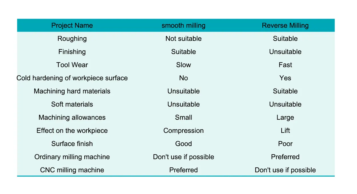
6. Comparison summary table of the selection of smooth milling and reverse milling, see table 1 for details.
Conclusion
To summarize, the selection of the milling method in the milling process should be based on several factors.
These include the drawing of the part, the processing technology requirements, the material of the part, and the condition of the machine tool.
All of these factors should be considered comprehensively.
Processing plane, it is recommended to use end milling processing methods; processing grooves, teeth and molding surfaces such as the use of circumferential milling processing methods.
When machining cast iron and hard materials with high surface roughness on a milling machine, use reverse milling as much as possible to avoid damaging the tool.
For roughing, reverse milling is used as much as possible due to the hard skin and unevenness of the material surface;
For semi-finishing and finishing, generally use the smooth milling process to improve the surface quality of the parts.
Ordinary milling machine processing parts, preferred reverse milling processing mode; CNC machine tool processing parts, preferred downstream milling processing mode.
Through observation, let beginners find that the surface quality of parts processed by smooth milling is good, and the surface of parts processed by reverse milling will have burrs and poor finish.
Reasonable selection of smooth milling and reverse milling processing mode, can improve processing quality, improve processing efficiency and tool life.

