
Rapid prototyping is a key link in modern product development, especially when making complex structural parts, the time and cost required often account for a large part of the overall development.
Although rapid prototyping (RP) and rapid tooling (RT) technologies are closely related to physical prototype manufacturing, they have certain materials, quality, and performance limitations.
Additionally, RT technology has a long conversion cycle, and it often fails to meet surface quality and accuracy requirements, requiring secondary processing.
Although traditional machining can manufacture prototypes, it is inefficient due to its poor flexibility and insufficient adaptability to complex shapes.
On the contrary, numerical control machining (NC machining) and high-speed machining (HSM) provide new possibilities for rapid prototyping.
Combining the experience of the aviation and mold industries, engineers can use block or bar stock as blank materials through CNC programming and efficiently manufacture rapid prototypes on CNC machine tools.
The practice has proved that reasonable processing flow and process selection can realize the manufacture of metal rapid prototypes.
Processing process and characteristics of prototype manufacturing by NC machining
The method of directly using the whole blank material for CNC machining differs from the conventional machining theory. Therefore, we must consider the unique processing characteristics when designing the rapid prototyping process for NC machining.
First, product designers usually focus on the process and cost of mass production rather than the ease of prototyping.
For example, if casting is chosen, the designer might specify a small and uniform wall thickness to enhance strength.
However, from the perspective of NC machining, this design may result in too much machining area and lack of support during flipping, which can easily lead to deformation, thus affecting the control of part size.
Second, NC machining usually requires removing a large amount of material at once, leading to a low material utilization rate (between 5% and 30%). The concentration of processes can also cause significant deformation.
When machining multiple faces, we require multiple clamping, which increases the difficulty of installing the reference docking and leads to machining deformation and surface quality issues.
Therefore, general machining principles and programming methods are difficult to meet the requirements of rapid prototyping.
We can adopt the following machining process to address problems such as single-piece production, integral materials, and multi-faceted machining, as shown in Figure 1.

Figure 1 Prototype manufacturing process based on NC machining
Process of rapid manufacturing of metal prototypes by NC machining
There are many problems in prototype manufacturing based on NC machining. The following mainly addresses the processing principles of parts, cutting force and temperature, deformation treatment, tool and machining parameters, optimization of tool trajectory, clamping, etc.

1. Division of machining procedures
On CNC machine tools, the process of machining rapid prototype parts usually adopts the tool concentration sequencing method, rough and fine machining sequencing method, and sequencing method according to machining parts.
However, for overall blank machining, we must remove a large margin during rough machining, and complete all processes in one direction within a single clamping, making the process concentration particularly evident.
To gradually release the generated machining deformation and reduce it, we must adopt the processing principle of separating rough and fine stages: rough first, then fine. This is divided into three processes: rough, semi-fine, and fine machining.
For the problem of multi-faceted machining, the method of uniform machining from multiple faces and arranging appropriate aging processes can control the overall deformation of the parts, but it increases the difficulty of installation and positioning in the actual machining process.
Most rapid prototype parts require processing on both inner and outer surfaces. We divide these surfaces into primary, secondary, working, and non-working categories.
We should not follow the conventional primary-first method. Instead, process secondary surfaces first, then primary surfaces.
Start with non-essential surfaces, then reverse installation to process the working surface.
Follow the principle: surface first, then hole. Reference first, then other features.
Process simple shapes before complex ones.
Process parts with lower precision first, then higher precision parts. Start with dimensions that have large tolerances, then process small-tolerance dimensions.
2. Clamping and positioning of workpieces
The positioning position should consider the consistency of the position after flipping.
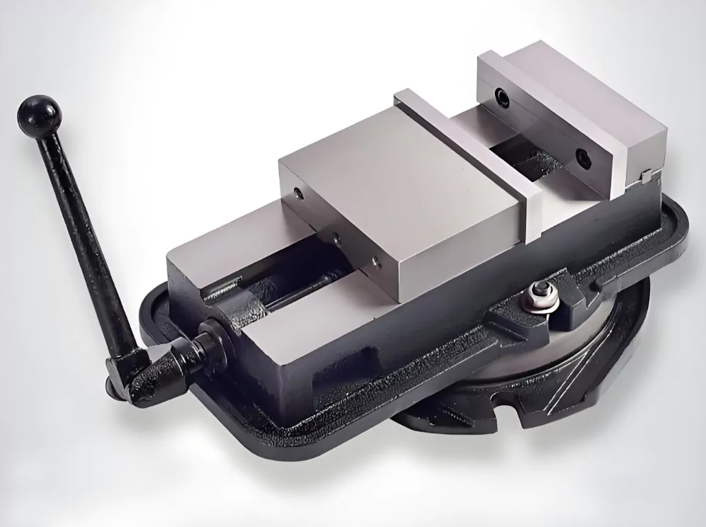
We generally use universal fixtures for clamping rapid prototypes, with pressure plate clamping methods being the most common.
Clamp several suitable areas of the excess material surface of the blank of the whole material, and process each surface.
Finally, we leave only a very thin lap in the clamping position on the rapid prototype workpiece, making it easy to separate the processed workpiece from the blank.
")
Universal fixture (picture)
However, after turning over, the internal area of the part may not be supported, which may cause processing deformation during processing and make it difficult to control the surface processing quality.
Although the cutting force can be reduced by selecting reasonable tools and cutting parameters and optimizing tool trajectories without auxiliary support, various auxiliary supports should be used to increase the rigidity of the parts.
For example, vacuum adsorption, adding auxiliary mechanical support, casting low melting point materials to reinforce parts, and universal pressing plates are used for combined clamping.
")
Vacuum suction cup (picture)
Vacuum adsorption has low clamping force, causing some issues.
A solution is to add auxiliary support in weak areas.
Alternatively, injecting a molten solution can help resist cutting forces.
This ensures the tool removes excess material based on calculated parameters.
")
Workpiece clamping (picture)
3. Selection of tools and cutting parameters
Currently, commonly used tool materials include high-speed steel, cemented carbide, diamond, polycrystalline cubic boron nitride (PCBN), ceramics, etc.
High-speed steel and cemented carbide are commonly used in rapid prototyping milling cutters, which are suitable for processing ferrous metals, non-ferrous metals, and non-metals such as engineering plastics.
Polycrystalline diamond (PCD) materials have high thermal conductivity, high hardness, high wear resistance, and low friction coefficient, and are suitable for high-speed cutting of engineering plastics and non-ferrous metals.
Carbide tools are usually used for ferrous metals of general hardness, and PCBN or ceramic insert tools are often used for milling hardened metals.
")
Common tools (picture)
Since the strength and hardness of the materials used in rapid prototyping are generally low, the hardness requirements of the tool are not high.
To improve prototype accuracy, and processing efficiency, and reduce deformation, good thinning ability is essential.
Using tools with high thermal conductivity and sharpness helps achieve this. Cutting parameters with high cutting speed, small cutting depth, and high travel speed are also necessary.
These reduce temperature and rebound elasticity caused by tool-workpiece contact, enhancing processing accuracy.
The cutting parameters generally adopt high cutting speed, extremely small feed per tooth, and cutting depth.
Roughing is selected according to the conventional method. The semi-finishing allowance is generally slightly larger than the conventional one to compensate for deformation.
During finishing, the intermediate tolerance method is generally adopted for the processing dimensions of key parts to avoid over-tolerance.
4. Optimization of tool path
For CNC machining, tool path is a key factor affecting machining efficiency and surface quality. The tool path of prototype NC machining needs to be standardized with optimized parameters.
(1) Roughing cutting strategy
In the roughing process, the use of rapid prototyping technology can effectively reduce deformation and improve efficiency.
To ensure the accuracy of multi-region machining, it is key to adopt the equal-layer cutting method, rather than simply machining from one region to the bottom. The cutting path of each layer can include parallel cutting and circular cutting.
Especially in high-speed cutting, the feed speed should be reduced or a smooth transition trajectory should be used to reduce impact.
In addition, before each layer of rough cutting, cutting along the periphery of the part at a lower speed helps to reduce the inertial impact on the part wall and ensure machining accuracy.
(2) Semi-finishing cutting strategy
Due to the use of tools of different diameters for roughing and finishing, roughing inevitably produces residual uncut areas.
Semi-finishing processes these residual uncut areas while retaining the finishing allowance.
At present, some software such as UG can check the size of the residual area by establishing a small plane model of the roughing area and comparing it with the machined part.
In rapid prototyping, semi-finishing mostly uses the contour cutting method.
To ensure uniform force during cutting, the semi-finishing along the contour of the area should adopt constant down milling or reverse milling.
(3) Finishing cutting strategies
During the finishing cutting process, the application of rapid prototyping technology can effectively improve the size, shape accuracy, and surface roughness of the parts.
The processing methods include projection processing and contour cutting, and their envelope trajectories are different.
In surface machining, to obtain ideal surface accuracy, the steep wall surface is usually processed by contour cutting, while the gentle surface is processed by projection machining.
Rapid prototyping technology can optimize the cutting process by combining the finishing strategy of slope analysis.
When the wall of the part is very thin, projection machining will cause deformation to increase due to the influence of cutting force.
At this time, contour cutting with a very small cutting depth is also an effective choice.

(4) Discussion on tool entry and exit methods
General tool entry and exit methods:
Straight entry and exit method
During the machining process, a ball-end milling cutter and “row cutting method” are used for operation.
The row-cutting method refers to the track of the cutting points of the tool on the surface of the part being row by row, and the row spacing is determined according to the machining accuracy requirements.
If the entry point cuts into the workpiece vertically, the tool will enter the workpiece surface from top to bottom, resulting in poor safety and low surface quality.
Therefore, this method is generally not recommended unless there are special restrictions on the surface contour.
Approximate entry and exit method
The first cut of the tool should be from the outside of the surface, and the last cut should also return to the outside of the surface when exiting.
Although this solves the problem of feed and retract, each line of feed and retract still exists on the machined surface, which may cause residual allowance, thus affecting the surface quality and causing inconvenience to subsequent processing.
Some CAD/CAM software has a tool path control function that can approximately solve this problem.
For example, in MasterCAM, the steps include: selecting “Tool Path” > “Surface Machining” > “Finishing” > “Surface Streamline”, and then setting the relevant parameters to generate the tool path.
Generate tool paths for large surfaces.
A more practical method is to create a larger surface or expand the machined surface while generating the machined surface.
Generate tool paths through this larger surface to ensure that each line of the tool does not feed and retract within the machined surface, thereby facilitating subsequent processing and ensuring the quality of the machined surface.
5. Processing simulation
The purposes of processing simulation include the following aspects:
(1) Avoid collision:
Simulation can detect potential collision problems between the tool and the workpiece, fixture, and machine tool in advance to avoid damage during actual processing.
(2) Optimize machining paths:
Through simulation, the tool movement path can be optimized, unnecessary movement can be reduced, and machining efficiency can be improved.
(3) Verify program correctness:
Ensure that the CNC machining program (such as G code) is correct to avoid incorrect instructions that cause tool damage or workpiece scrapping.
(4) Improve machining accuracy:
By previewing the tool path, potential errors in the path can be discovered, so that adjustments can be made in advance to improve the accuracy of the final product.
(5) Save costs:
Reduce trial and error costs and machine tool downtime in actual machining, and improve production efficiency.
This type of simulation is widely used in CNC machining in mold manufacturing, aerospace, automotive parts, and other high-precision and high-complexity machining fields.
Example of prototype manufacturing based on NC machining
Begin with
XX Company developed the XX750 racing concept car, the key component of which is the gearbox cover.
To ensure that the prototype can withstand alternating loads, high temperatures, and machining accuracy during high-speed movement, a metal prototype that is closest to the actual requirements must be adopted.
Although the rapid prototyping (RP) method is still in the experimental stage, due to its large deformation after sintering, casting is prone to defects such as pores, looseness, and slag inclusions, resulting in a decrease in strength, and the part hole system and assembly surface need to be processed after casting.
Finally, the NC direct processing of forged aluminum was adopted to meet the product strength and dimensional accuracy requirements, and a prototype experiment was carried out, as shown in Figures 2 to 5.
Before prototype manufacturing
We carried out a virtual prototype and simulated assembly and movement to ensure the model wouldn’t require modifications during manufacturing. The part has a complex shape and structure, and the hole system size and position accuracy requirements are high.
The part wall is thin, with an average wall thickness of only (2 to 3) mm.
We used a universal fixture and adjusted the installation position. After three clampings, we successfully processed all upper and lower surface profiles, ribs, hole systems, and inclined holes. We prevented tool collisions by refining the processing program and simulating the process.
We process the keyhole position last and use the intermediate tolerance method to ensure quality.
The tool selects a sharp high-speed steel tool for rough processing and a PCD tool for fine processing.
Compared with other methods, it has the characteristics of a short processing cycle, high processing accuracy, and low cost.

Figure 2. Three-dimensional prototype of gearbox cover

Figure 3. Photo of processing on the HV45NC machine tool


Conclusion
The current rapid prototype RP and rapid mold RT still have certain limitations in the rapid manufacturing of metal prototypes.
The NC machining method is an effective supplement to the rapid manufacturing of metal prototypes.
Adopting a reasonable processing flow and process strategy can facilitate the rapid manufacturing of metal prototypes based on NC machining of overall materials.
This also shows that the three methods of RP, RT, and NC machining are complementary prototype rapid manufacturing methods.

