
In high-volume pipe thread processing, although clamping the pipe with a fixture is simple, the large batch size and repeated labor still require a lot of installation time, which increases the manufacturing cost of a single piece.
According to the actual processing of machine tools, the development of a simple structure that is easy to operate, with a high degree of automation of the pipe fixture is an effective way to improve productivity.
We are introducing a hydraulic self-centering fixture suitable for new pipe threading machine tools in which the tool carries out a compound movement and the pipe remains immobile, which meets the production needs.
Requirements for fixture design
(1)Pipe clamping range (D) ф200~ф600 mm;
(2)Spindle speed 50~200r/min:
(3)Fixture center height 560 mm;
(4)Hydraulic station rated pressure 10 MPa.
General structural design of the fixture
1. Centering fixture general design
The CNC multi-cutter pipe threading machine tool is a pipe threading machine tool with a high degree of automation.
When designing the fixture, in addition to considering the functions required for the actual work, we specially designed an automatic clamping device.
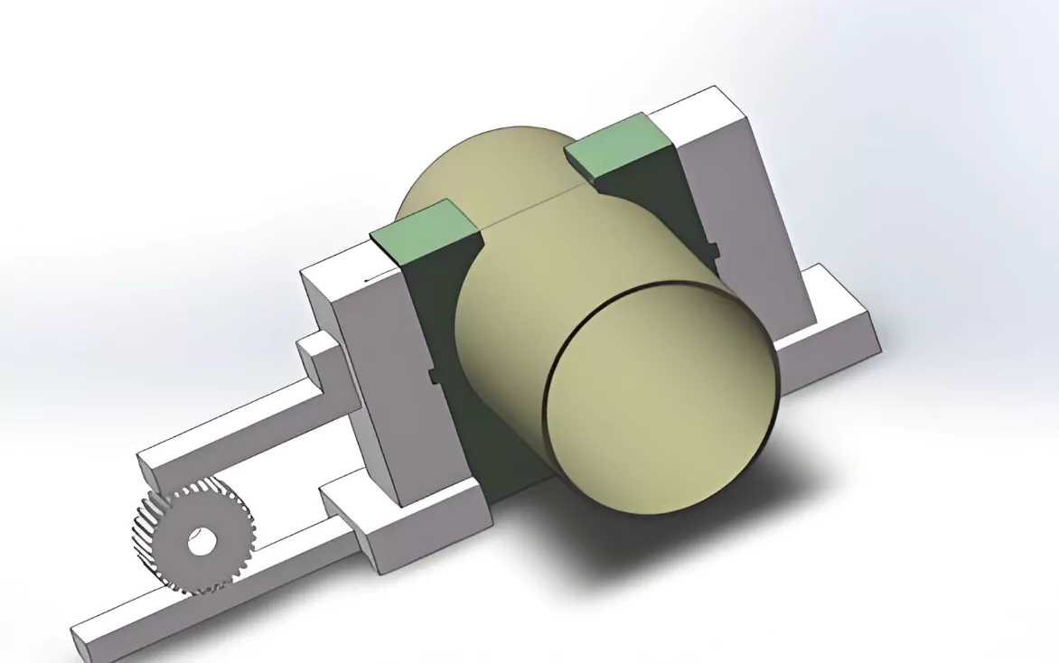
Fig. 1 shows the device, which mainly consists of the positive and negative screw 2, left slide 3, left V-block 4, left slide plate 8, right V-block 7, hydraulic motor 9, and fixture base 6.
When working, the hydraulic motor 9 drives the positive and negative screw 2, so that the slide plates 3 and 8 move in the opposite direction at the same time, thus driving the left and right V-shaped block fixed on the slide plate to clamp or relax the pipe and play the purpose of positioning and clamping.

Fig. 1 Centering fixture schematic
The fixture features a large clamping range, automatically adjustable clamping force, good rigidity, good flexibility, and a compact structure. It serves as a special fixture for large-diameter pipe threading machine tools.
2. Centering fixture adjustment and installation
When installing a self-centering fixture on a machine tool, it is necessary to ensure that the centerline of the fixture and the centerline of the spindle meet the requirement of coincidence, so it is necessary to adjust the position of the two V-blocks.
For this reason, the fixture adjustment structure shown in Fig. 2 is designed. Adjustment, through the left and right sides of the adjusting nut 3, bearing end caps 2, plane bearings 5, mounting shims 6, the axial force transmitted to the screw holder 1, through the adjusting nut to adjust the axial position of the screw 8.
And ultimately to make the center of the V-block and the center of the spindle coincide with the design of the machine tool fixture requirements, as shown in Figure 2.

Fig. 2 Clamp adjustment schematic
Force analysis of the fixture
1.Force Analysis of the Fixture
The primary role of the fixture is twofold:
To keep the tube in the correct position on the machine tool.
To prevent the tube from rotating or moving axially under the influence of cutting torque and axial cutting force during the machining process. Therefore, the fixture must withstand the corresponding cutting reaction force.

Fig. 3 Clamp force analysis
2.Cutting Reaction Forces Acting on the Fixture
As shown in Figure 3, the fixture experiences the cutting reaction force from the main cutting force Fc and the feed cutting reaction force Ff.
To simplify the arithmetic, only list the main force factors, according to the principle of statics to find out the size of the clamping force.
The cutting fixture experiences the total reaction force of

3.Clamping Force Calculation
Based on the friction force formula and the principle of hydrostatics to determine the positive pressure, the surface of the clamping element has a hardened mesh tooth pattern.
Its friction factor μ = 0. 7 ~ 0. 8, take μ =0. 7.

4.Force Characteristics of the V-Block
According to the force characteristics of the V-block, we get

To ensure reliable clamping, it is necessary to multiply by a safety factor, i.e. the actual required clamping force.

Fw for the most unfavorable conditions, from the static balance calculation of the clamping force;
Fj for the actual need for clamping force;
K for the safety factor, generally take K = 1. 5~3, roughing to take a large value, finishing to take a small value. Take K = 3.
5.Clamping Force and Reaction Force Relationships
According to the force relationship of the screw-nut pair, the torque applied to the screw

By substituting the main cutting force Fc = 2114 N and the axial cutting force Ff = 866 N into Equation (1), we obtain the combined cutting force on the fixture Fa = 2285 N.
Substituting Fa = 2285 N, μ = 0. 7 . ( 2), the positive pressure on the fixture is FN= 816 N.
The theoretical clamping force on the fixture is = 942 N. Substituting the positive pressure FN= 816 N.
6.Theoretical Clamping Force
Substituting positive pressure FN= 816 N. ( 3 ), the theoretical clamping force on the fixture is FW=942 N.
Substituting the theoretical clamping force FW= 942 N into equation ( 4), the actual clamping force required by the fixture Fj= 2826 N.
7.Torque Calculation
Due to the selection of single-head threads, the thread rise angle is

Check the friction factor f = 0. 08 ~ 0. 1, take f =0. 9, then the equivalent friction angle

Substitute the actual clamping force required by the fixture Fj= 2826 N, the equivalent friction angle, and the thread rise angle into Eq. ( 5) to obtain the torque on the screw

Clamp control system
The plunger hydraulic motor (1QJM001-0.06) with a rated torque of 95 N*m supplies the power for the automatic centering fixture. It can be infinitely adjusted within the speed range of 8 ~ 1000 r/min.
As shown in Fig. 4, during operation, the throttle valve 7 controls the speed of hydraulic motor 10.
We adjust the torque of the hydraulic motor using the pressure-reducing valve 5 and pressure relay 8.
A three-position, four-way solenoid valve 9 changes the steering of the hydraulic motor, which is used for clamping and unclamping.
All relays and solenoid valves are switched by the embedded PLC of the CNC control system.

Fig. 4 Schematic diagram of clamp hydraulic control
Conclusion
The practice has proven: The automatic centering fixture introduced in the paper has a simple structure, easy to operate, and solves the problem of clamping when machining large-diameter, large-inertia tubes.
In mass production, the fixture can quickly clamp the workpiece, accurate and reliable action, and high productivity, to meet the actual requirements of machine tool production.

