
In the actual production process, often encountered in the processing of a variety of different shapes and sizes of thin-walled pipe fittings, in the process of processing is easy to deformation.
Preventing its deformation is necessary to achieve the part drawing and stability requirements of the exploration method.
The processing of thin-walled parts is a more difficult problem in turning and milling pins. Thin-walled parts have poor rigidity and weak strength and are very easy to deform in machining, so the shape and position error of the parts increase. It is not easy to ensure the quality of the parts’ processing.
Leading factors affecting the machining accuracy of thin-walled tube workpieces
1. Easy deformation by force.
A thin-walled workpiece easily deforms under the action of the clamping force, affecting its dimensional and shape accuracy.
When the three-jaw chuck is used to clamp the workpiece’s outer circle to process the workpiece’s inner hole, the outer circle will slightly become a triangle under the action of the clamping force.
Although the processing is obtained after a cylindrical hole, but when the jaws are loosened to remove the workpiece, due to the elastic recovery, the outer circle is restored to cylindrical, while the inner hole becomes curved and triangular.
2. Easy to deform by heat.
Cutting heat will cause thermal deformation of the workpiece, making it difficult to control its size.
For thin-walled metal workpieces with large coefficients of linear expansion, the thermal deformation caused by the cutting heat will have a significant impact on its dimensional accuracy.
3. Vibration prone to deformation.
Under the action of the cutting force, the radial force on the workpiece will cause it to undergo bending deformation.
This deformation affects features such as the outer surface of the workpiece, including grooves. As a result, the tool cutting will experience uneven force, which can easily lead to vibration.
This vibration affects the workpiece’s size, shape, positional accuracy, and surface roughness.
Methods to reduce and prevent deformation of thin-walled parts machining
1. Axial clamping fixture should be used.
When turning and milling thin-walled workpieces, try not to use radial clamping and prioritize the axial clamping method.
To achieve axial clamping, the workpiece is clamped by an axial clamping sleeve (threaded sleeve) at the end face.
Due to the clamping force being distributed along the axial direction of the workpiece and considering its axial rigidity, clamping deformation is not easy to occur.
2. Increase the clamping contact surface.
The use of open seam sleeve or some special soft claw.
The contact surface increases, the clamping force is evenly distributed on the workpiece, and the workpiece is not easy to produce local deformation when clamping.
3. Reasonable selection of tool geometry parameters and cutting parameters.
In short, reduce the cutting force and heat generated during cutting.
4. Adequate pouring of cutting fluid.
Most of the heat will be concentrated in the chips and the tip of the tool when cutting. Cutting fluid has a cooling, lubrication, chip removal, and anti-rust function.
By fully pouring cutting fluid, it can effectively cool down the cutting temperature and reduce the thermal deformation of the workpiece.
5. Increase the process rib.
Some thin-walled workpieces have special production of several process ribs in the clamping part to enhance the rigidity.
This helps reduce the workpiece’s deformation by distributing the clamping force onto the process rib. After processing, the process rib is removed.
Thin wall processing case
1. The thin-walled parts of the difficulty analysis
The following chart shows material duraluminum 2A12T4, which uses hollow cylindrical blanks. The inner cavity needs to be milled out on all four sides.

The outer wall has four Φ26 diameter holes, along with some assembly screw holes and threaded holes.
The maximum diameter of the outer circle is 180mm ± 0.05mm, with the minimum wall thickness being 3mm. This ensures that the roundness and deformation are less than or equal to 0.15mm.
Accurate positioning and alignment are also required to ensure the positional accuracy of the inner four aspects, the inner cavity, and external features.
2. The process route before improvement is as follows
(1) Lathe three-jaw counter-weighing internal rough turning external circle, and then clamping external turning internal circle. Inside and outside the circle on one side to leave 1mm allowance
(2) Machining center Rough milling the shape of the inner cavity, leaving 1mm allowance on one side, and find the correct inner square to open the rough 4 Φ26 holes, leaving 2mm allowance on one side.
(3) Stress relief and stabilization
(4) Lathe machine Second roughing 0.5mm allowance on one side of inner step circle and 0.5mm allowance on one side of outer circle.
(5) Machining center: Secondary roughing 0.5mm on one side of inner cavity shape
(6) Stabilization
(7) Lathe Flat two end surfaces to size, semi-finish turning inner circle, fine turning inner circle to size
(8) Machining center Precision milling internal cavity shape to size
(9) Lathe machine Precision turning of outer circle to size
(10) Machining center Precision milling the shape of all holes and grooves on the outside.
3. Main processing methods and problems before improvement
(1) Rough finishing milling of the shape of the inner cavity with the fixture involves a slit sleeve outer tire, which is clamped fixed with a three-jaw chuck.
This clamping method creates a radial force on the workpiece. The thin-walled workpiece deforms under this force, resulting in a roughly triangular shape.
Due to the significant deformation caused by this clamping, a 2mm allowance is left on a single side.
This allowance is divided into two rough milling steps. Aging processes follow two steps.
The first rough milling primarily focuses on relieving much stress, with slightly higher clamping force.
The second rough milling uses slightly lower clamping force. The phenomenon that occurs when machining in this way is as follows:
The workpiece wall will gradually become thinner during the roughing process.
As a result, the workpiece rigidity is gradually reduced. The amount of deformation will increase progressively.
When the workpiece is clamped flat, the clamping force will gradually decrease.
This reduction in clamping force will cause the workpiece to loosen gradually. As a result, the workpiece may warp upward or rotate during machining.
Precision milling will extend the production cycle by preventing clamping deformation. By keeping the clamping force as small as possible, the cutting amount will be reduced accordingly.
(2) Rough precision turning of the internal cavity is done with a special brass soft claw.
The claw clamps the cylindrical turning internal circle. The same principle applies to ensure that the workpiece will deform under the clamping force.
Even without processing, the thin-walled workpiece will deform due to tight clamping.
The workpiece will absorb the heat from cutting, which will release stress. This deformation is difficult to control.
Precision turning cylindrical use of two tops, both ends of the clamping force by the lathe tailstock live top of the top to obtain.
Two fixtures are respectively with the workpiece left and right two internal circle and end face with tight and then fine-turning of the outer circle.
Problems arise when fine-turning internal deformation is not controlled.
The fine-turning of the external round is supported by two fixtures that hold the internal round.
The external round is then turned. At this point, the external circular runout coaxiality is not an issue.
However, when unloading the workpiece, it will return to its original state.
This happens because the workpiece is subjected to the cutting force and cutting heat.
As a result, the amount of deformation will further increase.
This processing only ensures a uniform wall thickness, but the deformation amount cannot be controlled.
(3) The final finishing milling of outer holes and slots uses two tops.
This processing in the middle of the overhanging wall thin rigidity is not good, punching will be up and down chatter.
Processing of the shape of the surface features but also to ensure that the positional relationship with the inner cavity of the shape of the quadrilateral, it is not easy to find the right.
4. Improved process route analysis
(1) lathe three-jaw counter-support inner circle rough turning outer circle, and then clamping the outer circle rough turning inner circle
(2) Machining center Rough milling inner cavity four sides, rough milling 4 large holes on one side to leave 1mm allowance
(3) Stress relief and stabilization
(4) Lathe Flatten both end faces, leave 0.5mm allowance on one side of the outer circle, and semi-finish turn the inner circle.
(5) Stress relief and stabilization
(6) Lathe Precision turning of both end faces and inner circle to size.
(7) Machining center Precision milling of internal cavity shape
(8) Lathe Fine turning of outer circle to ensure the round runout and size requirements.
(9) Machining center Precision milling all shapes of outer side
5. Main machining methods after improvement and the effect achieved.
(1) Maching process
When using the open-seam socket tire to cover the outer circle, there is no difference between rough milling the inner cavity quadrangle and the one before the improvement.
The three-jaw clamping tire is used to mill the inner square.
When rough milling the outer holes, the special big soft claw clamps the outer circle at the right end of the workpiece.
The correct inner quadrangle is found from the left end of the workpiece, and the rough round holes are opened.
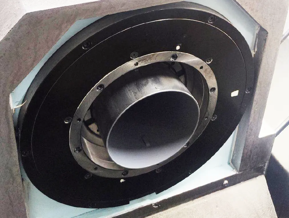
The tools shown in Figure 2 and Figure 3 are used for the precision milling of the inner cavity.


Note:
1. The spiral cover, along with the light blue threaded part at the upper end of the tire body, fastens and applies pressure to the upper end of the workpiece.
The spiral cover’s through-hole diameter is 2mm larger than the workpiece’s bore diameter. The workpiece’s wall thickness is 3mm, ensuring the pressure contact surface width remains 2mm.
This design ensures that the fastening pressure does not interfere with the tool’s shape while cutting the workpiece’s inner cavity.
2. On the support ring, the outer wall of the blue part of the tire’s main body works together with the upper blue part on the inner side of the wall.
This structure interacts with the workpiece’s outer circle, blocking the workpiece’s upper end from moving left, right, forward, and backward.
Additionally, it provides positioning support to ensure that the workpiece’s center of rotation remains the same during each clamping operation.
3. The workpiece to be processed
4. Tire body, as shown
3-Tire body inside the lower end of a 15mm deep a step circle and the bottom of the workpiece with the outer circle, the middle purple part of the black rubber material and the need for milling part of the outer wall gap with the role of anti-vibration and anti-fibrillation.
5. Small block
This part serves as the finishing touch of the tire set. It aligns with the groove on the outer wall of the main body of the tire set.
Additionally, it extends into the Φ26 round inner wall of the workpiece, making contact and blocking movement.
At the same time, it plays a role in positioning, ensuring accuracy, and limiting the workpiece’s clockwise rotation.
Since the tool rotates clockwise, it exerts a force that would otherwise cause the workpiece to rotate in the same direction.
The screw holes on the block and the threaded holes on the tire body are fastened to ensure that the block will not vibrate and fall off during machining.
Fig. 4 below shows the form of the small stopper and the inner wall of the workpiece Φ26 circle.

Achieved results
The workpiece is positioned on the support ring within the tire set, ensuring stability.
A black rubber shockproof layer in the middle prevents fibrillation. Additionally, a 15mm deep step circle is used for positioning, enhancing system rigidity.
These improvements significantly enhance cutting parameters, leading to increased production efficiency.
Before the improvement, the process took 30 minutes; after the improvement, it was reduced to 15 minutes.
This set and tire tools can also be shared with the fine-turning cavity, reducing production costs.
(2) Rough precision turning cavity
The principle of the rough precision turning cavity designed tire and the precision milling cavity four-square are the same, except that this time, the small block only restricts the effect of workpiece rotation, as shown in Figure 5.

The workpiece is subjected to the axial clamping force of the screw cover, ensuring that the clamping force does not cause deformation.
When turning the inner hole, the workpiece remains almost completely free, meeting the technical requirements.
Before the improvement, the only solution to reduce the deformation caused by the radial clamping force was to decrease the clamping force, which required reducing the cutting amount.
After the improvement, clamping deformation is no longer a concern, allowing for an increase in the cutting amount.
This enhances productivity, reducing the process time from 35 minutes before the improvement to 25 minutes after.
(3) Precision milling of the outer wall holes in the tire tool as follows Figure 6.


