Table of Contents
CNC machining technology plays a vital role in impeller manufacturing. Engineers design impellers as mechanical parts composed of complex curved surfaces. They are core components that impact the performance of power machinery, especially fluid machinery like pumps, compressors, and turbines.
Engineers and technicians have long struggled to shape the blades of small gas turbine impellers, which are integral and feature complex curved surfaces. Over time, blade designs evolved from radial straight blades to twisted blades with backward bends and forward inclinations. The new blades are also longer and thinner, making machining more difficult and demanding higher CNC machining precision.
CNC machining enables higher precision and complex shapes, addressing challenges in impeller manufacturing.
The main difficulties include the following aspects:
1. Complex Shape of Impellers:
The impeller’s intricate design—featuring curved surfaces, narrow grooves, and blades with varying cross-sections—poses significant challenges for traditional machining. Achieving precise manufacturing requires advanced CNC equipment capable of multi-axis processing.
2. High Precision Requirements:
Impeller machining demands exceptional precision to maintain balance and ensure optimal performance. Any dimensional deviations, surface roughness, or tolerance issues directly affect the impeller’s functionality, making high-accuracy processing equipment and techniques essential.
3. Material Processing Challenges:
Impellers are often made from tough materials such as stainless steel, titanium alloys, and nickel-based alloys. These materials offer excellent corrosion and heat resistance but are difficult to machine, leading to tool wear and increased processing costs.
4. Specialized CNC Programming:
Due to the impeller’s complex geometry, specialized programming techniques are required to generate CNC machining paths. Optimizing tool selection, machining paths, and cutting parameters is crucial for enhancing machining efficiency and ensuring high-quality results.
5. Clamping and Positioning Difficulties:
Securing impellers, particularly those with thin blades or irregular shapes presents a challenge. Ensuring the workpiece is clamped firmly without causing deformation is a critical aspect of the machining process.
6. Precision Inspection:
Impeller inspection demands high-precision equipment, such as Coordinate Measuring Machines (CMM), to assess the blade surfaces and key dimensions. Additionally, dynamic balance testing is vital to ensure the impeller’s stability during operation, ensuring its long-term reliability.
High-performance four- and five-axis CNC machining machines are now widely used to accurately process impellers with complex shapes. However, high-performance four- and five-axis CNC machining machines are generally expensive and have high processing costs.
The processing cycle of the integral impeller is long and inefficient, resulting in high manufacturing costs. Improving efficiency and reducing costs are key research focuses for engineers in the impeller processing industry.
Titanium alloys are widely used for impellers due to their excellent mechanical properties, but they are difficult to machine, especially for new integral impellers, and their machining quality significantly impacts engine performant ce. Therefore, how to efficiently develop high-quality titanium alloy integral impellers is a problem worthy of in-depth research.
Generally speaking, the processing difficulty of titanium alloys mainly includes the following points:
1. High strength and low thermal conductivity: Titanium alloys have high strength and high hardness, but low thermal conductivity. Cutting heat concentrates on the tool and workpiece, rapidly raising tool temperature and increasing wear and damage.
2. High chemical activity: At high temperatures, titanium alloys react with tool materials (like carbides), forming built-up edges or adhering to the tool, increasing wear. We refer to this phenomenon as “sticking tool” or “chemical wear.”
3. Low elastic modulus of titanium alloys causes deformation and vibration during cutting, affecting accuracy and surface quality. This elastic deformation may also cause unstable contact between the tool and the workpiece, increasing the risk of tool breakage.
4. Unstable cutting force occurs when cutting titanium alloys due to curling and uneven chip fracture. The fluctuation of cutting force not only affects the processing accuracy but also easily causes tool vibration and fracture.
5. Titanium alloys tend to harden during cutting, creating a hardened layer that increases processing difficulty, impacts tool performance, and reduces tool life and efficiency.
6. Titanium alloys require tools with high wear resistance, heat hardness, and adhesion resistance, like PCD and CBN tools, and coatings such as TiAlN. The selection and optimization of tools become very critical and also increase the processing cost.
Analysis of machining difficulties
The impeller CNC machining requires high accuracy, with IT6 dimensional tolerance and Ra1.6 surface roroughnessThe blade surface is a free-form surface with a large curvature variation. The impeller flow channel is narrow, making tool collisions with adjacent blades easy. The blades are long, exceeding 50mm, and the blade thickness is thin, with the thickest part only 2.8mm. It is very easy to cause vibration during CNC machining, affecting the surface machining quality. As shown in Figure 1.

Figure 1 Titanium alloy integral impeller blade
The impeller material is titanium alloy TC4, which has poor cutting performance. At the same time, the elastic modulus of titanium alloy is small (about 1/2 of 45# steel). In CNC machining, small cutting forces can cause large deformation, leading to sticking, tool disengagement, and wear, compromising surface quality and geometric accuracy. The processing of titanium alloy materials often uses lower cutting parameters, and its processing efficiency is generally very low. The CNC machining efficiency of the integral impeller made of titanium alloy is lower than that of other materials.
CNC machining of the impeller involves three steps: blade rough grooving, rough machining, and finishing. Rough grooving removes most material between the blades while finishing ensures shape and surface quality. However, since the blades are cantilevered, they lack rigidity during finishing, making them prone to elastic deformation and instability during milling.
a. Free-Form Surface and Spot Milling Challenges:
The impeller blade features a free-form surface, which requires point milling during the finishing process. However, the changing cutting angle of the spot milling tool results in fluctuating cutting forces and varying directions. This unpredictability causes excessive vibrations, leading to vibration marks on the blade’s surface, which in turn compromises surface quality.
b. Insufficient Blade Rigidity and Profile Accuracy:
During finishing, the low rigidity of the blade can lead to small cutting forces in spot milling that impact the accuracy of the blade profile. To address this issue, it’s essential to determine the appropriate finishing allowance, ensure sufficient blade rigidity, and select the right tool parameters to minimize cutting forces, thereby preserving the blade’s profile accuracy.
The difficulty of the overall impeller CNC machining in this case lies in the milling process. Generally, the milling process accounts for more than 80% of the total CNC machining time. At the same time, the milling quality directly affects the performance of the impeller. How to improve the CNC milling efficiency and blade forming quality is the focus of this article.
Key points of the multi-axis CNC milling process
The CNC milling process of the impeller generally includes rough grooving to remove large allowance, semi-finishing milling of the blade and hub surface, and finishing milling of both the blade and hub.
To improve the CNC machining efficiency and quality of the impeller, we use the following process: rough grooving, finishing milling of the blades and finishing the hub surface.
This arrangement saves theoretically 1/3 of the milling time by removing the semi-finishing of the blade and rough sweeping of the hub surface.
The rough grooving process removes about 1/3 of the material, plays a key role in material removal, releases internal stress, and causes stress deformation, impacting the impeller’s geometric dimensions. Actual machining measurements show that the size of the hole changes by about 0.02mm after the impeller is slotted.
To ensure strict dimensional accuracy and reduce the influence of stress deformation, we must arrange the milling process reasonably. We arrange a fine turning sequence between rough and fine milling of the impeller to prevent stress release and deformation, ensuring strict dimensional accuracy.
The focus of the rough grooving of the impeller is CNC machining efficiency and cost. Generally, manufacturers use low-end four-axis linkage CNC machine tools as much as possible to achieve rough grooveing. Choosing the right fine milling allowance, strengthening blade rigidity, and determining the appropriate cutting amounts crucial for the difficulty and quality of fine machining.
This paper improves impeller rough grooving efficiency by optimizing the path and process parameters, making the state of the impeller more suitable for fine machining. During fine machining, suitable tools and cutting parameters are selected to enhance the NC machining efficiency and quality of the titanium alloy impeller under high speed and high feed.
Rough machining tool position planning
Rough machining aims to quickly remove the blank allowance, and its focus is on the machining efficiency in CNC machining. Optimize the tool for a high feed rate and maximum cutting depth to remove more material quickly. Rough machining does not require high surface quality. In CNC machining, selecting large-sized tools as much as possible when grooving improves cutting performance and efficiency. The impeller’s process arrangement eliminates semi-finishing, requiring strict control of its state after rough grooving due to the unstable cutting during finishing.
1. the allowance of the blade after rough machining should not be too small. Due to the low elastic modulus and high hardness of titanium alloy, the blade’s rigidity is poor, and the rough grooving allowance cannot be too small. This can affect forming accuracy, surface quality, and dimensional accuracy, while also shortening tool life. At the same time, it should not be too large, otherwise it is difficult to obtain high-quality surface roughness. According to experience, the allowance is generally between 2 and 4mm.
2. Ensure uniform allowance after rough grooving to prevent blade deformation and surface transition marks during CNC machining and finishing.
3. Shape the blade allowance into a tower, increasing from top to root, to enhance rigidity and reduce finishing vibrations.
The following introduces CNC machining grooving path planning for the overall impeller grooving, according to the above requirements.
a. Press the impeller horizontally onto the machine tool. This method is suitable for impellers where the blades do not overlap or distort when viewed axially. Otherwise, the groove won’t fully remove the blank allowance, preventing proper removal between the flow channels.
b. Perform profiling milling on the blades offset according to the allowance. This method has a uniform allowance, but in CNC grooving, milling the offset blades involves half of the tool (ball head and side edge) in cutting, limiting the feed rate and affecting tool life.
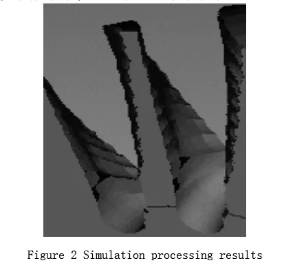
c. This paper proposes a layer-by-layer tool path from top to bottom, following the impeller flow channel direction, to control the processing area between flow channels and shape the blade reserve into a tower shape, ensuring blade rigidity. Figure 2 shows the situation after simulating the CNC machining.
Table l Three rough machining methods

This paper adopts the method of grooving layer by layer along the flow channel. CNC machining is highly efficient, with a uniform blade margin after grooving and sufficient rigidity. It also requires a shorter blade length, preventing excessive blade engagement and reducing cutting force e. There is less tool interference, good chip removal, and sufficient cooling.
Blade finishing and hub surface finishing.g
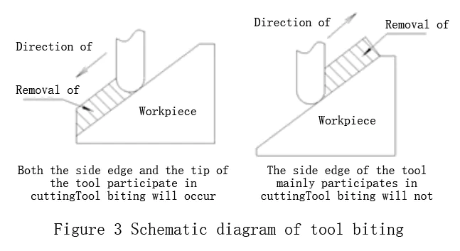
Tool gnawing during ramp milling in CNC machining of titanium alloys limits the cutting feed rate. The cutting conditions are unstable, and the tool is prone to chipping due to low linear cutting speed near the center. CNC machining shows that upward milling has better tool life than downward milling, as the tool’s center doesn’t cut, reducing gnawing and chipping. Figure 3 is a schematic diagram of the tool gnawing situation.
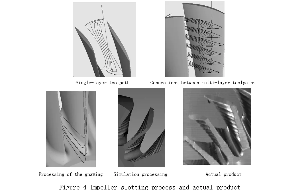
To avoid frequent tool lifting during gnawing and rough grooving, we establish a parallel tool path with the upper layers of the flow channel to the XY plane using an equal-height milling path. For the lower layers, we move from bottom to top and apply an upward milling tool path. We achieve rough grooving of the impeller by post-processing the tool path on a low-end four-axis CNC machine. Figure 4 shows the impeller grooving process and the actual product.
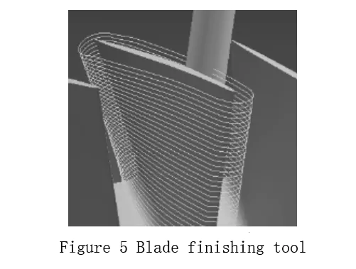
Blade finishing and hub surface finishing are the key parts of impeller CNC machining. Their machining accuracy and surface quality have a great impact on the performance of the impeller. UG uses variable axis contour milling to program blade finishing. The cutting method is down milling, with a step length of 0.3mm per layer and a surface roughness of 0.01mm. Figure 5 shows the blade finishing tool path trajectory.
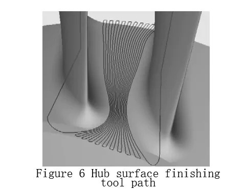
The hub surface finishing uses a ZIG-ZAG bidirectional reciprocating cutting method, enabling bidirectional CNC machining along the flow channel direction. This cutting method alternates between forward milling and reverse milling during the cutting process, which improves processing efficiency. Figure 6 shows the tool path trajectory of the hub surface finishing bottom sweeping.
Selection of impeller finishing tools and cutting parameters
In CNC machining, unstable cutting during finishing milling makes selecting tool and machining parameters crucial for the efficiency and surface quality of titanium alloy impellers. An important way to solve the unstable cutting state during finishing is to select a suitable finishing tool. Based on titanium alloy’s processing characteristics and our experience, we typically choose fine-grained cemented carbide YL10.2 for finishing tools.
The selection of the back angle of titanium alloy machining tools is the most critical. Increasing the back angle improves tool durability but may cause chipping. Typically, an 8°–10° angle is chosen, as it reduces front cutting-edge wear due to the small contact area. A smaller front angle should be selected, and the front angle value should be within 10°. The helix angle has a greater impact on the tool front angle. Increasing the helix angle boosts the cutting front angle, avoiding excessive front angle that weakens the tool while reducing cutting force and extending tool life.
According to experience, the helix angle of the titanium alloy tool should be between 30° and 40°. Increasing the helix angle boosts the cutting front angle, avoiding excessive front angle that weakens the too while reducing cutting force and extending tool life. Therefore, it is essential to strictly control the profile of the impeller finishing tool.
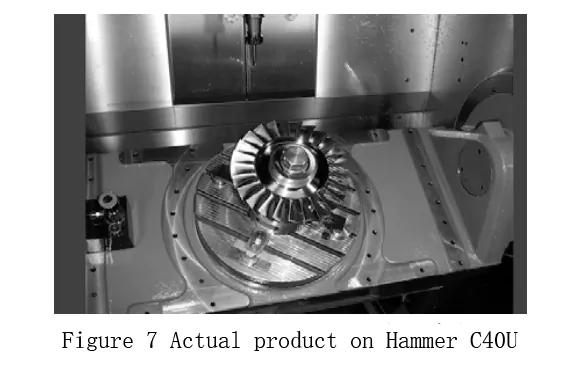
Another factor that has an important impact on the quality and efficiency of CNC machining is the matching of cutting parameters and the selection of machine tools. This paper uses the Hammer C40U five-axis CNC machine tool to process the impeller, with a speed of 10000rin/min and a feed rate of 900mm/min. The machining process efficiently produces a titanium alloy integral impeller with good surface quality. Figure 7 shows the actual product after processing on the Hammer C40U.
Conclusion
In the process of CNC machining, manufacturers mainly use expensive multi-axis high-performance CNC machine tools to machine impellers. How to reduce costs and improve efficiency and quality is the focus of research by engineering and technical personnel. The tool contour significantly affects the blade’s forming quality during finishing. If the tool’s actual profile deviates from the theoretical one, the profile error will impact the blade’s quality.
a. This paper focuses on the tool position planning in the rough grooving stage. I compared the advantages and disadvantages of three roughing methods and proposed a layer-by-layer CNC grooving method along the flow channel direction. This method offers high efficiency, uniform reserve, and good blade rigidity, and is ideal for fine machining.
b. In fine machining of the impeller, we select optimal CNC tool and cutting parameters, using the Hammer C40U five-axis high-speed machining center for efficient, high-quality machining with high speed and feed

