Table of Contents
In recent years, with the rapid development of industries such as automobiles, defense, aviation, and aerospace, and the application of new materials such as aluminum alloys, intelligence, personalization, and refinement have become the new driving force for manufacturing development. The factory received a batch of special connector orders that require internal right-angle processing. Figure 1 shows the technical requirements of the order.
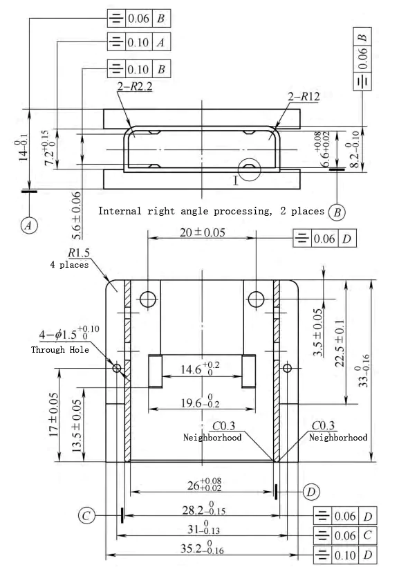
Figure 1 Schematic diagram of parts
Processing process analysis
1. Part Overview and General Processing Approach
This batch of parts consists of 20 pieces, made from 2A12-T4 aluminum alloy, a high-strength, hard aluminum. Although this material is easy to process, its processing requirements remain strict. According to the part diagram (Figure 1), we can easily complete the part’s cavity, cavity wall boss, right-angle grooves on both sides, anti-slip grooves on two planes, and hole processing on the machining center. These common processes can be efficiently finished using a universal vise clamp combined with multiple clamping.
2 . Challenges in Internal Right-Angle Processing
However, the two internal right-angle processing processes in Figure 1 face great difficulties. The length is 26mm, the tolerance limit is 0.06mm, the cavity width requirement is 6.6mm, and the symmetry must reach 0.06mm. In addition, the overall surface quality requirements are high, and scratches are not allowed. Conventional CNC milling processing methods are prone to leaving R angles at internal right angles due to the cylindrical structure of the milling cutter, which cannot meet the processing requirements, as shown in Figure 2. Therefore, it is necessary to explore more advanced processing methods to achieve precise internal right-angle processing.
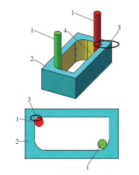
Figure 2 Schematic diagram of residual R angle
1. End mill 2. Connector 3. Residual R angle
4. Internal right angle to be processed
Common traditional process methods have many limitations in meeting the technical requirements of this product:
1. Precision casting method:
Although the precision casting method can process complex shapes, it is expensive and not suitable for small-batch production, resulting in poor economic efficiency.
2. Traditional slotting method:
It requires special machine tools and large equipment investment, so the overall cost is high, which limits its flexibility and applicability.
3. Planing method:
Although the planning method can process certain shapes, its processing efficiency is low, especially in mass production.
4. Ordinary milling method:
It has strong applicability, but it cannot effectively complete the internal right angle processing in a small cavity, and it is easy to produce an R angle, which cannot meet the precision requirements.
In addition, these traditional methods are also insufficient for the processing capabilities of closed cavities, stepped cavities, blind holes, or internal right angles and keyways with obstructed shoulders, and cannot meet the increasingly complex processing needs. Therefore, it is necessary to find more advanced processing technology to solve these problems.

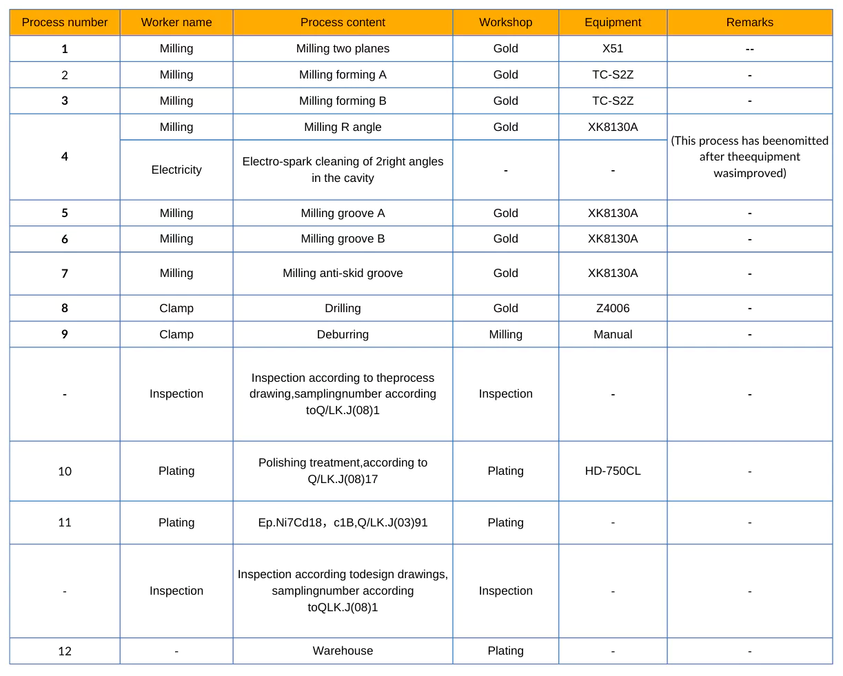
For the processing of the two internal right angles in Figure 1, we can only use an EDM machine for discharge corrosion processing. This method requires operators to frequently repeat positioning and clamping, and at the same time, the accuracy of the tooling fixtures and electrodes is extremely high. Such requirements lead to higher costs and lower processing efficiency, and increase the turnover links between processes, further increasing the risk of surface damage and scratches on parts. The overall process is shown in Table 1, including the electrical processing process (red part).
Advantages of spindle orientation
By adjusting the position of the workpiece and the tool in real time, we can significantly improve processing accuracy, leading to better cutting precision. Additionally, machining efficiency can be enhanced by reducing the frequency of tool changes and adjustments, as well as optimizing machining paths. This not only shortens overall machining time but also contributes to greater productivity.
The system supports a wide range of cutting methods, which helps expand machining capabilities and allows the processing of workpieces with complex shapes and angles. Moreover, by optimizing cutting angles, we can reduce tool wear, minimize non-uniform wear, and extend the life of the tools.
Finally, by improving cutting conditions, we can achieve higher surface quality, resulting in a superior surface finish after machining.
Solution ideas and solutions
The process design for this part should focus on reducing the number of clamping times to achieve one-time clamping for completing machining and forming. The machining center uses paired angular contact ball bearings for the front and rear supports, effectively withstanding radial and axial loads, enabling micro-slotting functions on the milling machine.
Under the guidance of the “Four New Ideas” (new knowledge, new technology, new process, and new method), I think it is feasible to transform the CNC machining center and add the “spindle arbitrary angle orientation” function. This function allows the operator to control the Z axis to move up and down after the spindle stops and locks. We can combine the self-made slotting tool to achieve micro-slotting processing at a specified angle, which will help us effectively complete the internal right-angle processing, as shown in Figures 3 to 5.
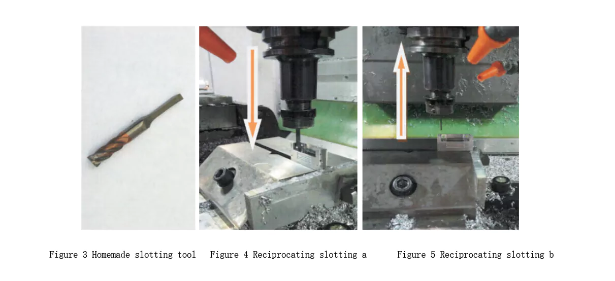
After completing the inner cavity finishing of the part, the worker removes the residual allowance of the inner R angle using the micro-slotting method. This approach effectively ensures dimensional accuracy while avoiding the need for the EDM process. The overall process is shown in Table 1, which excludes the red EDM process. By realizing the micro-slotting function, the worker optimizes the processing technology and improves both overall efficiency and quality.
Table 1 Mechanical Process Card
Realization of Equipment Function
The factory has equipped the VMC600 machine tool with the mainstream FANUC serial spindle on the market. Although it only has the basic spindle orientation function, to meet the needs of this small batch directional slotting production and take into account the principle of “creating the greatest benefit at the lowest cost”, the factory can carry out secondary development of the original machine tool without increasing any hardware investment to achieve the directional slotting function at any angle.
The control of spindle orientation is mainly composed of hardware connection, parameter setting, and PMC ladder diagram. The specific implementation process includes the following steps:
1. Parameter setting:
According to the parameter setting and related signal configuration of 0i-D, as shown in Table 2 and Table 3, ensure that the system can correctly identify and respond to instructions.
2. Control process:
Through reasonable parameter configuration, ensure that the spindle can be oriented at the specified angle, thereby realizing the required micro-slotting processing function.
Table 2 Parameter setting

Table 3 Related signals

Note: When the external setting of spindle orientation is not used, the spindle position offset is calculated as (NO.4077) + (NO.4031). However, when the external setting of spindle orientation is used, the parameter 4031 becomes invalid, and the spindle position offset is determined by (NO.4077) + (G78, G79).
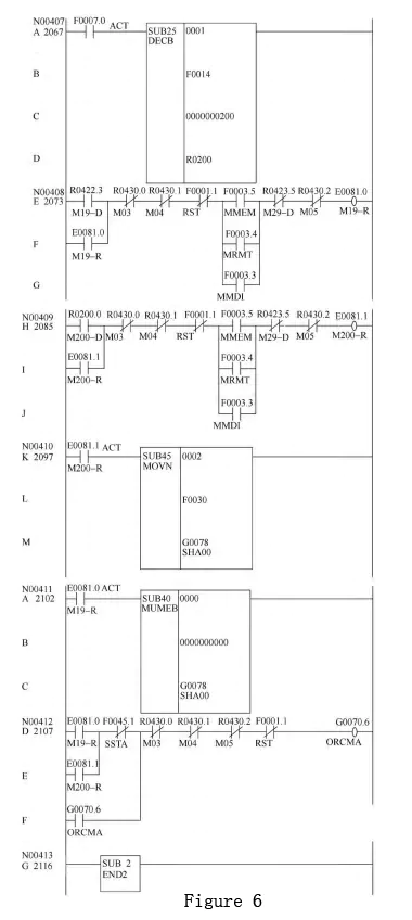
Ladder diagram compilation. Take the ladder diagram of 0i-D compiled based on the original ladder diagram of the VMC600 machining center as an example for explanation (see Figure 6).
Note: The above ladder diagram is for reference only. M code decoding and FIN signal processing are required.
Control instructions:
(1) Use M200 B** to modify the different values assigned to G78 and G79, and use multiple function instructions to achieve multiple fixed angle positioning.
(2) When M19 executes, it assigns 0 to G78 and G79, and the spindle offset becomes the value in NO.4077.
(3) When executing M200 to assign the value in B** to G78 and G79, the system sets the spindle offset to NO.4077 + B**.
(4) When programming, you can use B** to specify the spindle offset. The target angle value B=**×4 095/360. The relationship between the values in G78 and G79 and the offset angle is a linear relationship between [0, 4095] and [0, 360].
Implementation of part processing
(1) Use a small diameter tool, such as φ2mm, to perform corner-clearing processing, so that the residual internal R angle allowance is as small as possible. Before micro-slotting processing, the parallelism between the tool edge and the cavity wall should be adjusted first. Method: Run M200 B** in MDI mode, orient the spindle, test cut, and then repeatedly change the value of B** until there is no step on the cavity wall.
(2) Skills: Manually turn the slotting tool edge to the specified angle, and you can view the spindle offset in DNG445. The offset = NO.4077 + B**, and the value of B** can be obtained in reverse.
Note: Before the production task is completed, the adjusted tool and tool holder cannot be displaced and cannot be disassembled. If you need to remove the tool holder from the spindle, you should note the direction of the tooltip and keep the same direction when installing it again.
(3) Micro-slotting program:
O0001
G21
N102G0G17G40G49G80G90
G90G54X50.Y50.
M200B1024 (spindle oriented at a certain angle)
G43H1Z50.
6Z1.
M98P0002L100
G90G0Z50.
M5
G91G28Z0.
G28Y0.
M30
O0002
G91G01Z-33.5F2000
Z33.5
X-0.1
M99
Conclusion
Through the above examples, we can see that the improvement of equipment functions has significantly optimized the internal right-angle processing technology of the product and improved production efficiency and quality. After mass production testing of the test piece, the improved micro-slotting function showed stable and reliable performance, and the processing program proved its correctness and flexibility. This technology is not only widely applicable and economical but also demonstrates high practical value, making it worthy of promotion and large-scale application.
We have mainly improved this function for the FANUC serial spindle system, but we still need to further study how to improve analog spindles or other CNC systems and demonstrate safety and reliability to ensure that the expected results are achieved when it is put into production.
What is spindle orientation technology?
Spindle orientation technology aligns the spindle to a specific angular position, enabling precise tool positioning. It is critical for processes like cutting, drilling, or milling where angular accuracy impacts the final product.
How does spindle orientation improve internal right-angle processing?
Spindle orientation ensures that tools are positioned exactly at 90 degrees or other required angles to the workpiece. This precision eliminates deviations, resulting in clean and accurate internal right-angle features.
What tools are compatible with spindle orientation technology?
Tools like end mills, corner rounding cutters, and right-angle tools are commonly used in conjunction with spindle orientation technology to achieve precise internal angles.
Can spindle orientation technology reduce processing time?
Yes. By accurately aligning the tool without repeated manual adjustments, spindle orientation technology minimizes setup time and reduces overall machining time.
Is spindle orientation technology suitable for all CNC machines?
Most modern CNC machines support spindle orientation, but older models may require upgrades or retrofitting to incorporate this functionality.
What role does programming play in optimizing internal right-angle processing?
Programming defines the precise angular alignment of the spindle and toolpath. Advanced CNC systems with spindle orientation technology allow automated, consistent alignment for complex internal geometries.
How does spindle orientation improve tool life in right-angle processing?
Accurate tool positioning reduces unnecessary stress and wear on cutting tools, leading to longer tool life and consistent performance in internal right-angle processing.
What industries benefit from spindle orientation in right-angle machining?
Industries such as aerospace, automotive, and medical device manufacturing benefit from spindle orientation for creating precise internal features in components like housings, brackets, and specialized connectors.

